


197
Reference Manual
00809-0100-4444, Rev AC
Appendix A: Implementing a Universal Transmitter
January 2015
Implementing a Universal Transmitter
A.13 Generic manufacturer sensors
A.13.1 Generic manufacturer sensor to Rosemount 8732
transmitter
A.13.2 Identify the terminals
First check the sensor manufacturer’s manual to identify the appropriate terminals. Otherwise,
perform the following procedure.
Identify coil and electrode terminals
1. Select a terminal and touch an ohmmeter probe to it.
2. Touch the second probe to each of the other terminals and record the results for each
terminal.
3. Repeat the process and record the results for every terminal.
Coil terminals will have a resistance of approximately 3-300 ohms.
Electrode terminals will have an open circuit.
Identify a chassis ground
1. Touch one probe of an ohmmeter to the sensor chassis.
2. Touch the other probe to the each sensor terminal and the record the results for each
terminal.
The chassis ground will have a resistance value of one ohm or less.
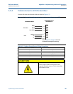
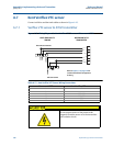
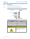
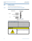
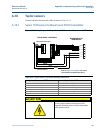
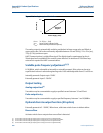
A.13.3 Wiring connections
Connect the electrode terminals to Rosemount 8732 terminals 18 and 19. The electrode shield
should be connected to terminal 17.
Connect the coil terminals to Rosemount 8732 terminals 1, 2, and 3
.
If the Rosemount 8732 Transmitter indicates a reverse flow condition, switch the coil wires
connected to terminals 1 and 2.
Do not connect mains or line
power to the magnetic flowtube
sensor or to the transmitter coil
excitation circuit.