


Reference Manual
00809-0100-4444, Rev AC
Section 3: Advanced Installation Details
January 2015
41
Advanced Installation Details
Section 3 Advanced Installation Details
Introduction . . . . . . . . . . . . . . . . . . . . . . . . . . . . . . . . . . . . . . . . . . . . . . . . . . . . . . . . . . . . . . . page 41
Hardware switches . . . . . . . . . . . . . . . . . . . . . . . . . . . . . . . . . . . . . . . . . . . . . . . . . . . . . . . . . . page 41
Hardware switches . . . . . . . . . . . . . . . . . . . . . . . . . . . . . . . . . . . . . . . . . . . . . . . . . . . . . . . . . . page 41
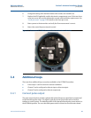
Additional loops . . . . . . . . . . . . . . . . . . . . . . . . . . . . . . . . . . . . . . . . . . . . . . . . . . . . . . . . . . . . page 43
Connect discrete input . . . . . . . . . . . . . . . . . . . . . . . . . . . . . . . . . . . . . . . . . . . . . . . . . . . . . . page 51
Process reference connection . . . . . . . . . . . . . . . . . . . . . . . . . . . . . . . . . . . . . . . . . . . . . . . . page 52
Coil housing configuration . . . . . . . . . . . . . . . . . . . . . . . . . . . . . . . . . . . . . . . . . . . . . . . . . . . page 52
3.1 Introduction
This section details some of the advanced installation considerations when utilizing the
Rosemount
8700M Magnetic Flowmeter Platform.
3.2 Safety messages
Note
The electronics stack is electrostatically sensitive. Be sure to observe handling precautions for
static-sensitive components.
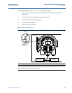
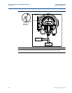
3.3 Hardware switches
The electronics are equipped with four user-selectable hardware switches. These switches set
the Alarm Mode, Internal/External Analog Power, Transmitter Security, and Internal/External
Pulse Power.
Definitions of these switches and their functions are provided below. To change the settings, see
below.
3.3.1 Alarm mode
If an event occurs that would trigger an alarm in the electronics, the analog output will be driven
high or low, depending on the switch position. The switch is set in the HIGH position when
shipped from the factory. Refer to Table 5-1 on page 88 and Table 5-2 on page 88 for analog
output values of the alarm.
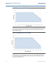
The electronics may store energy after power is removed. Allow ten
minutes for charge to dissipate prior to removing electronics compartment
cover.