


162
Reference Manual
00809-0100-4444, Rev AC
Section 9: Troubleshooting
January 2015
Troubleshooting
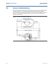
9.5 Basic troubleshooting
When troubleshooting a magmeter, it is important to identify the issue. Tab le below provides
common symptoms displayed by a magmeter that is not functioning properly. This table
provides potential causes and suggested corrective actions for each symptom.
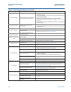
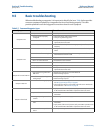
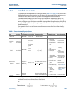
Table 9-7. Common Magmeter Issue
Symptom Potential cause Corrective action
Output at 0 mA
• No power to transmitter • Check power source and connections to the transmitter
• Analog output improperly
configured
• Check the analog power switch position
• Verify wiring and analog power
• Electronics failure • Verify transmitter operation with an 8714D Calibration Standard or
replace the electronic stack
• Blown fuse •Check the fuse and replace with an appropriately rated fuse, if
necessary
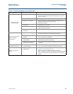
Output at 4 mA
• Transmitter in multidrop mode • Configure Poll Address to 0 to take transmitter out of multidrop
mode
• Low Flow Cutoff set too high • Configure Low Flow Cutoff to a lower setting or increase flow to a
value above the low flow cutoff
• PZR Activated • Open PZR switch at terminals 5 and 6 to deactivate the PZR
• Flow is in reverse direction • Enable Reverse Flow function
•Shorted coil •Coil check – perform sensor test
•Empty pipe •Fill pipe
• Electronics failure • Verify transmitter operation with an 8714D Calibration Standard or
replace the electronics stack
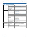
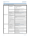
Output will not reach 20 mA
• Loop resistance is greater than
600 ohms
• Reduce loop resistance to less than 600 ohms
• Perform analog loop test
• Insufficient supply voltage to
analog output
• Verify analog output supply voltage
• Perform analog loop test
Output at 20.8 mA
• Transmitter not ranged properly • Reset the transmitter range values –
see URV (Upper Range Value) on page 36
• Check tube size setting in transmitter and make sure it matches the
actual tube size – see Line size on page 36
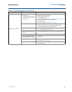
Output at alarm level
• Electronics failure • Cycle power. If alarm is still present, verify transmitter operation with
an 8714 D Calibration Standard or replace the electronics stack
• Open coil circuit • Check coil drive circuit connections at the sensor and at the
transmitter
• Analog output diagnostic alarm
is active
• See AO diagnostic alarm on page 89
• Coil power or coil current is over
limit
• Check coil drive circuit connections at the sensor and at the
transmitter
• Cycle power. If alarm is still present, verify transmitter operation with
an 8714 D Calibration Standard or replace the electronics stack
• Connected to incompatible
sensor
• See Implementing a Universal Transmitter on page 171