


20
Reference Manual
00809-0100-4444, Rev AC
Section 2: Installation
January 2015
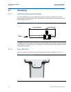
Quick Installation and Startup
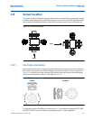
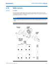
2.10.2 Alignment
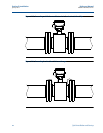
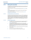
1. On 1.5 through 8-inch (40 through 200 mm) line sizes, Rosemount requires installing
the alignment spacers to ensure proper centering of the wafer sensor between the
process flanges.
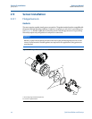
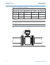
2. Insert studs for the bottom side of the sensor between the pipe flanges and center the
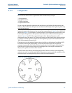
alignment spacer in the middle of the stud. See Figure 2-9 for the bolt hole locations
recommended for the spacers provided. Stud specifications are listed in Table 2-7.
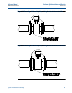
3. Place the sensor between the flanges. Make sure the alignment spacers are properly
centered on the studs. For vertical flow installations slide the O-ring over the stud to
keep the spacer in place. See Figure 2-9. Ensure the spacers match the flange size and
class rating for the process flanges. See Table 2-8.
4. Insert the remaining studs, washers, and nuts.
5. Tighten to the torque specifications shown in Table 2-9. Do not over-tighten the bolts
or the liner may be damaged.
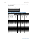
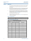
Table 2-7. Stud Specifications
Nominal sensor size Stud specifications
1.5 through 8-in. (40 through 200 mm) CS, ASTM A193, Grade B7, threaded mounting studs
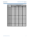
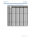
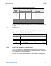
Table 2-8. Rosemount Alignment Spacer Table
Rosemount alignment spacer table
Dash no.
(-xxxx)
Line size
Flange rating(in) (mm)
0A15 1.5 40 JIS 10K-20K
0A20 2 50 JIS 10K-20K
0A30 3 80 JIS 10K
0B15 1.5 40 JIS 40K
AA15 1.5 40 ASME- 150#
AA20 2 50 ASME - 150#
AA30 3 80 ASME - 150#
AA40 4 100 ASME - 150#
AA60 6 150 ASME - 150#
AA80 8 200 ASME - 150#
AB15 1.5 40 ASME - 300#
AB20 2 50 ASME - 300#
AB30 3 80 ASME - 300#
AB40 4 100 ASME - 300#
AB60 6 150 ASME - 300#
AB80 8 200 ASME - 300#
DB40 4 100 EN 1092-1 - PN10/16
DB60 6 150 EN 1092-1 - PN10/16
DB80 8 200 EN 1092-1 - PN10/16
DC80 8 200 EN 1092-1 - PN25
DD15 1.5 40 EN 1092-1 - PN10/16/25/40
DD20 2 50 EN 1092-1 - PN10/16/25/40