


25
Reference Manual
00809-0100-4444, Rev AC
Section 2: Quick Installation and Start-Up
January 2015
Quick Installation and Start-Up
2.12 Wiring the transmitter
This wiring section covers the wiring between the transmitter and sensor, the 4-20mA output,
and supplying power to the transmitter. Follow the conduit, cable, and electrical disconnect
requirements in the sections below.
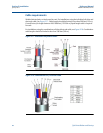
For sensor wiring diagrams, reference Electrical Drawing 08732-1504 in Appendix D Wiring
Diagrams.
For hazardous locations, reference Installation Drawings 08732-2060 and 08732-2062 in
AppendixC Approval Information.
For information on connecting to another manufacturer’s sensor, refer to Appendix A
Implementing a Universal Transmitter.
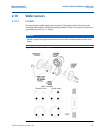
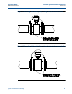
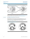
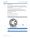
2.12.1 Conduit entries and connections
The standard conduit entries for the transmitter and sensor are 1/2” NPT. Thread adapters are
provided for units ordered with M20 conduit entries. Conduit connections should be made in
accordance with national, local, and plant electrical codes. Unused conduit entries should be
sealed with the appropriate certified plugs. The flow sensor is rated IP68 to a depth of 33 feet
(10 meters) for 48 hours. For sensor installations requiring IP68 protection, the cable grands,
conduit, and conduit plugs must be rated for IP68. The plastic shipping plugs do not provide
ingress protection.
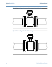
2.12.2 Conduit requirements
For installations with an intrinsically safe electrode circuit, a separate conduit for the
coil cable and the electrode cable may be required. See Installation Drawings in
AppendixC Approval Information.
For installations with non-intrinsically safe electrode circuit, or when using the
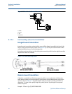
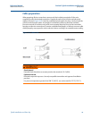
combination cable, a single dedicated conduit run for the coil drive and electrode cable
between the sensor and the remote transmitter may be acceptable. Bundled cables
from other equipment in a single conduit are likely to create interference and noise in
the system. See Figure 2-15.
Electrode cables should not be run together and should not be in the same cable tray
with power cables.
Output cables should not be run together with power cables.
Select conduit size appropriate to feed cables through to the flowmeter.