


153
Reference Manual
00809-0100-4444, Rev AC
Section 9: Troubleshooting
January 2015
Tro ubles hooting
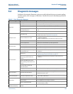
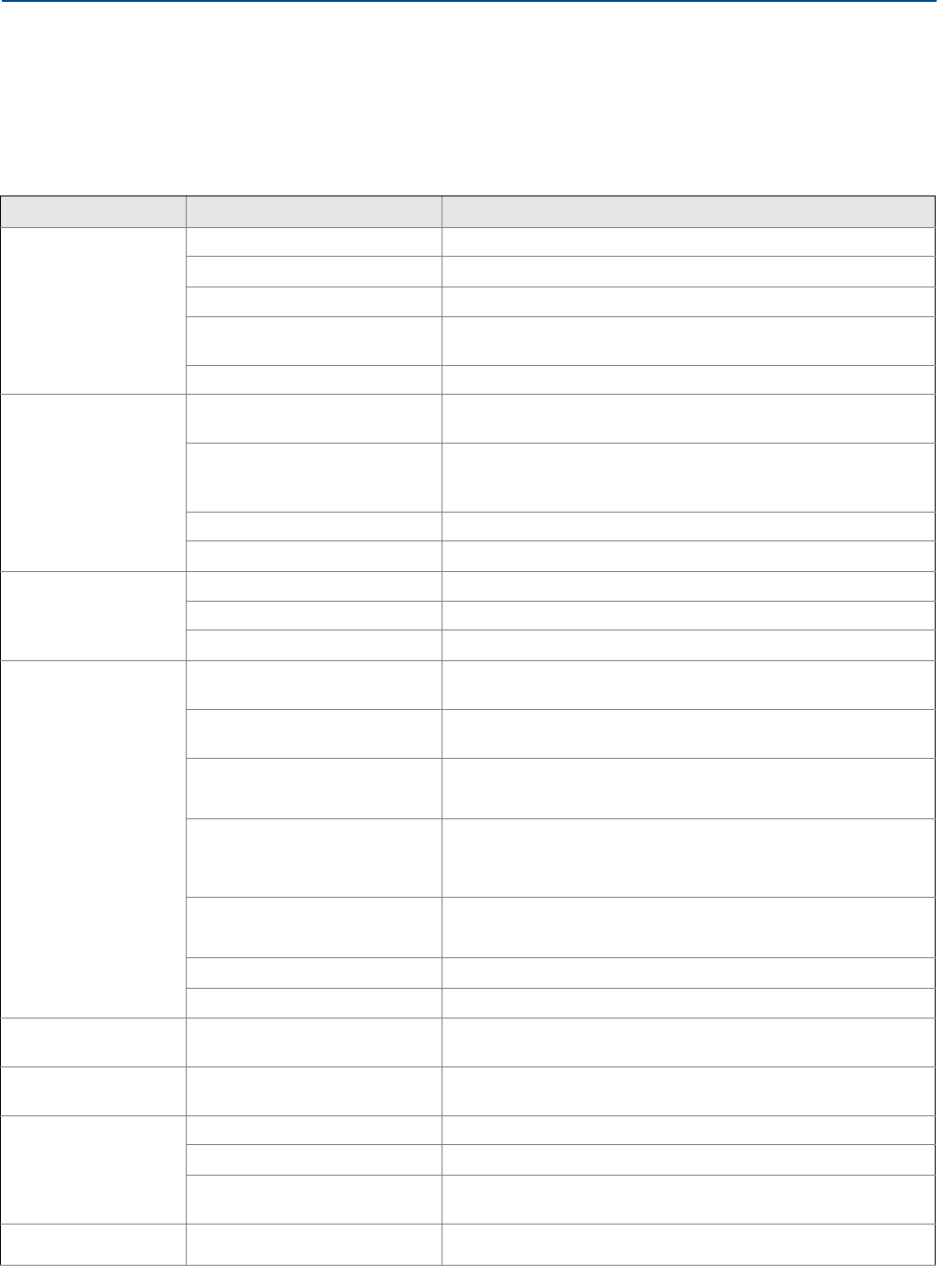
9.4 Diagnostic messages
Problems in the magnetic flowmeter system are usually indicated by incorrect output readings
from the system, error messages, or failed tests. Consider all sources in identifying a problem in
the system.
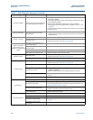
Table 9-1. Basic Diagnostic Messages
Error message Potential cause Corrective action
Empty Pipe
Empty pipe •None - message will clear when pipe is full
Wiring error •Check that wiring matches appropriate wiring diagrams
Electrode error • Perform sensor tests - see Table 9-8 on page 168
Conductivity less than 5
microSiemens per cm
• Increase conductivity to greater than or equal to 5 microSiemens per
cm
Intermittent diagnostic • Adjust tuning of empty pipe parameters - see Section 8.4.1
Coil Open Circuit
Improper wiring
• Check coil drive wiring and sensor coils
Perform sensor tests - see Table 9-8 on page 168
Other manufacturer’s sensor
• Change coil current to 75 mA - set calibration numbers to
10000550100000030
• Perform a universal auto-trim to select the proper coil current
Electronics board failure • Replace 8732EM electronics stack
Coil circuit open fuse •Return the unit to the factory for fuse replacement
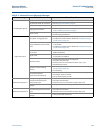
Auto Zero Failure
Flow is not set to zero • Force flow to zero, perform auto zero trim
Unshielded cable in use •Change wire to shielded cable
Moisture problems • See Table 9-8 on page 168
Auto-Trim Failure
No flow in pipe while performing
Universal Auto Trim
• Establish a known flow rate, and perform universal auto-trim
calibration
Wiring error
• Check that wiring matches appropriate wiring diagrams - see
Implementing a Universal Transmitter on page 171
Flow rate is changing in pipe while
performing Universal Auto-Trim
routine
• Establish a constant flow rate, and perform universal auto-trim
calibration
Flow rate through sensor is
significantly different than value
entered during Universal Auto-Trim
routine
• Verify flow in sensor and perform universal auto-trim calibration
Incorrect calibration number entered
into transmitter for Universal
Auto-Trim routine
• Replace sensor calibration number with 1000005010000000
Wrong sensor size selected • Correct sensor size setting - see Line size on page 36
Sensor failure •Perform sensor tests - see Table 9-8 on page 168
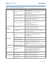
Electronics Failure Electronics self check failure
• Cycle power to see if diagnostic message clears
•Replace Electronics stack
Electronics Temp Fail
Ambient temperature exceeded the
electronics temperature limits
• Move transmitter to a location with an ambient temperature range of
-40 to 140 °F (-40 to 60 °C)
Reverse Flow
Electrode or coil wires reverse • Verify wiring between sensor and transmitter
Flow is reverse •Turn ON Reverse Flow Enable to read flow
Sensor installed backwards
• Install sensor correctly, or switch either the electrode wires (18 and 19)
or the coil wires (1 and 2)
PZR Activated
(Positive Zero Return)
External voltage applied to terminals
5 and 6
• Remove voltage to turn PZR off