30
Reference Manual
00809-0100-4444, Rev AC
Section 2: Installation
January 2015
Quick Installation and Startup
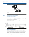
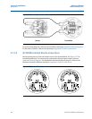
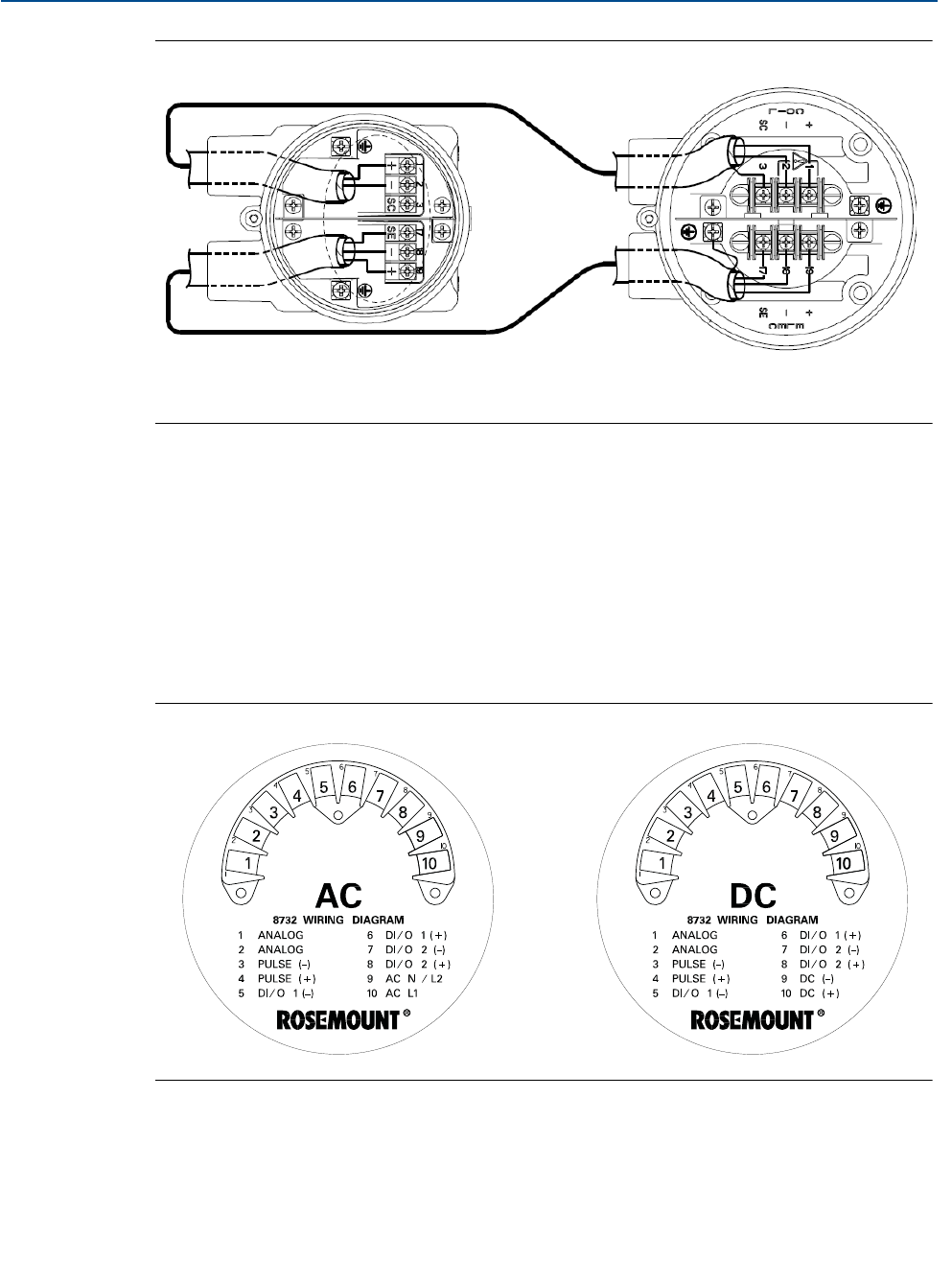
Figure 2-20. Remote Junction Box Views
Sensor Transmitter
For sensor wiring diagrams, reference the installation drawings in Appendix D Wiring Diagrams.
For hazardous locations, reference the drawings in Appendix C Product certifications.
2.12.4 8732EM terminal block connections
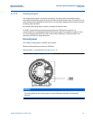
Remove the back cover of the transmitter to access the terminal block. See Figure 2-21 for
terminal identification. To connect pulse output and/or discrete input/output, reference
Appendix D Wiring Diagrams. For installations with intrinsically safe outputs, reference the
hazardous location installation drawings in Appendix C Product certifications.
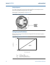
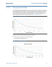
Figure 2-21. Terminal Block Connections


