


42
Reference Manual
00809-0100-4444, Rev AC
Section 3: Advanced Installation Details
January 2015
Advanced Installation Details
3.3.2 Transmitter security
The security switch on the 8732EM allows the user to lock out any configuration changes
attempted on the transmitter. No changes to the configuration are allowed when the switch is
in the ON position. The flow rate indication and totalizer functions remain active at all times.
With the switch in the ON position, access to review the operating parameters is available. No
configuration changes are allowed.
Transmitter security is set in the OFF position when shipped from the factory.
3.3.3 Internal/external analog power
The 8732EM 4-20 mA loop may be powered internally or by an external power supply. The
internal /external power supply switch determines the source of the 4-20 mA loop power.
Transmitters are shipped from the factory with the switch set in the INTERNAL position.
The external power option is required for multidrop configurations. A 10-30 VDC external
supply is required and the 4-20 mA power switch must be set to the EXTERNAL position. For
further information on 4-20 mA external power, see “Analog output” on page 31.
3.3.4 Internal/external pulse power
The 8732EM pulse loop may be powered internally or by an external power supply. The inter-
nal/external power supply switch determines the source of the pulse loop power.
Transmitters are shipped from the factory with the switch set in the EXTERNAL position.
A 5-28 VDC external supply is required when the pulse power switch is set to the EXTERNAL
position. For further information on the pulse external power, see “Connect pulse output” on
page 43.
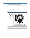
3.3.5 Changing hardware switch settings
To change the switch settings, complete the steps below:
Note
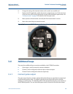
The hardware switches are located on the top side of the electronics board and changing their
settings requires opening the electronics housing. If possible, carry out these procedures away
from the plant environment in order to protect the electronics.
1. Place the control loop into manual control.
2. Disconnect power to the transmitter
3. Remove the electronics compartment cover. If the cover has a cover jam screw, this
must be loosened prior to removal of the cover.
4. Remove the LOI, if applicable.
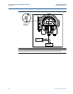
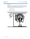
5. Identify the location of each switch (see Figure 3-1).