


FUEL SYSTEM (DFI) 3-11
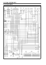
DFI Wiring D iagram
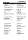
Terminal Names
1. Power Supply to Sensors (inlet air pres-
sure, a
tmospheric pressure, and throttle
sensors) from ECU.
2. Main Throttle Sensor Signal
3. Subth
rottle Sensor Signal for ECU
4. Atmospheric Pressure Sensor Signal
5. Water Temperature Sensor Signal (+)
6.7.
8.
–
9. Camshaft Position Sensor Signal ( +)
10. –
11. Cran
kshaft S ensor Signal (+)
12. –
13. Power Supply to ECU, Injectors, and Fuel
Pum
p
14. Sensor Ground (inlet air temperature,
water temperature, inlet air pressure, at-
mos
pheric pressure, vehicle-down, and
throttle sensors)
15. –
16
.
Ve
hicle-down Sensor Signal
17. Inlet Air Pressure Sensor Signal
18. Inlet Air Temperature Sensor Signal (+)
19
.
–
20. Speed S ensor S ignal
21. –
2
2.
C
amshaft Position Sensor Signal (–)
23. –
24. Crankshaft Sensor (–)
2
5.
–
26. ECU Power Source Circuit Ground to Bat-
tery (–) Terminal
27. Engine
Stop Switch Signal
28. Starter Lockout Switch Signal
29. Electric Starter Button Signal
30. Signa
l For Fuel Pump Relay
31. Subthrottle Valve Actuator Drive Signal
32. Subthrottle Valve Actuator Drive Signal
33. –
34. Tachometer Signal
35. Injector #2 Signal
36. Inje
ctor #1 Signal
37. Stick Coil #3 Signal
38. Stick Coil #2 Signal
39. Sti
ck Coil #1 Signal
40. Interlock Circuit Signal
41. Self-diagnosis Signal (generated by
gro
unding this terminal and shown by
FI indicator LED light)
42. –
43
.
Ba
ttery Power ON-OFF Signal
44. Subthrottle Valve Actuator Drive Signal
45. Subthrottle Valve Actuator Drive Signal
46
.
–
47. FI Indicator LED Light Signal
48. Injector #4 Signal
4
9.
I
njector #3 Signal
50. DFI System Ground
51. Ignition System Ground
5
2.
S
tick Coil #4 Signal
Part Name
A. ECU (Electronic Control Unit)
B. Crankshaft Sensor
C. Inlet Air Pressure Sensor
D. Water Temperature Sensor
E. Atmospheric Pressure Sensor
F. Inlet Air Temperature Sensor
G. Camshaft Position Sensor
H. Speed Sensor
I. Main Throttle Sensor
J. Subthrottle Sensor
K. Injectors #1, #2, #3, #4
L. Subthrottle Valve Actuator
M. Stick Coils #1, #2, #3, #4
N. Engine Stop Switch
O. Joint Connector D
P. see Electrical System chapter
Q. Ground Terminal
R. Ground Terminal
S. ECU Main Relay
T. Ignition Switch
U. FI Indicator LED Light
V. Tachometer
W. Speedometer
X. Ignition Fuse 10A
Y. Junction Box
Z. Fuel Pump Relay (for fuel pump and in-
jectors)
a. ECU Fuse 15A
b. Vehicle-down Sensor
d. Starter Relay
e. Joint Connector D
f. Sealed Battery
g. Fuel Pump
h. Self-diagnosis Terminal
j. Joint Connector B
k. Main F use 30A
m. Throttle B ody Assy Connector
n: Connector Locks
p: ECU C onnector