


3-58 FUEL SYSTEM (DFI)
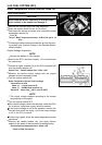
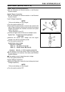
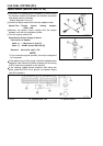
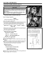
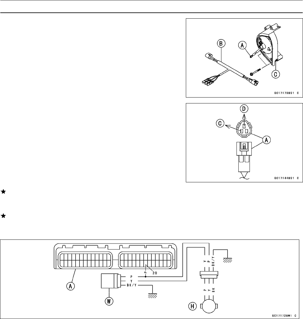
Speed Sensor (Service Code 24, 25)
•
Disconnect the speed sensor connector [A] and connect
the harness adapter [B] between the harness connector
and spe
ed sensor connector.
Engine Sprocket Cover [C]
•
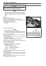
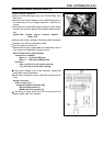
Connect a digital meter to the harness adapter leads.
Special Tool - Throttle Sensor Setting Adapter:
57001–1400
•
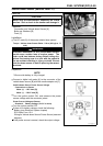
Measure the sensor output voltage with the engine
stopped, and with the connector joined.
•
Turn the ignition switch ON.
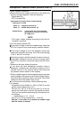
Speed Sensor Output Voltage at Sensor
Connections to Adapter
Meter (+) → Y/W (sensor Y) lead [C]
Meter (–) → BK/BL (sensor BK) lead [D]
Stan
dard:
Abou
t0.05∼ 0.07 V DC
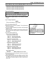
NOTE
○
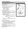
If you rotate the engine sprocket, t he output voltage will
be increased.
If the reading is out of the range, check the speed sensor
operation (see Electrical System chapter) and the wiring
to ECU (see wiring diagram in this section).
If the reading, speed sensor operation and wiring are
good, check the E CU for its ground, and power supply
(see ECU section).
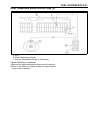
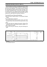
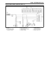
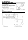
A. E CU W. Speedometer Unit H. Speed Sensor