


FUEL SYSTEM (DFI) 3-41
Main Thrott le Sensor (Service Code 11)
Output Voltage Inspection
•
Measure the output voltage at the main throttle sensor
in the same way as input voltage inspection, Note the
following.
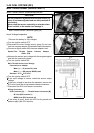
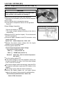
•
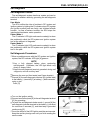
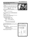
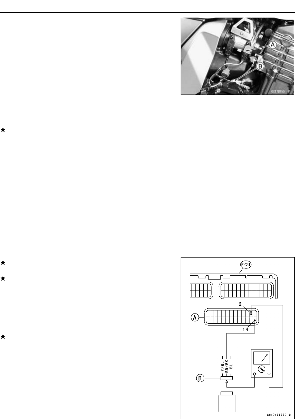
Disconnect the main throttle sensor (gray) [A] and con-
nect the harness adapter [B] between these connectors.
Special Tool - Throttle Sensor Harness Adapter :
57001–1538
•
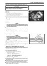
Start the engine and warm it up thoroughly.
•
Check idle speed to ensure the throttle opening is correct.
Idle Speed
Standard: 1 100 ± 50 r/min (rpm)
If the idle speed is out of the specified r ange, adjust it
(see Idle Speed Inspection in the Periodic Maintenance
chapter).
•
Turn off the ignition switch.
•
Measure the output voltage of the sensor with the engine
stopped, and with the connector joined.
•
Turn the ignition switch ON.
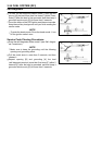
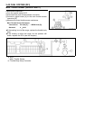
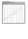
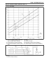
Main Throttle Sensor Output Voltage
Connections to Adapter
Meter (+) → W (sensor Y/W) lead
Meter (–) → BK (sensor BR/BK) lead
Standard :
0.99 ∼ 1.03 V DC (at idle throttle opening)
4.19 ∼ 4.39 V DC (at full throttle opening)
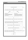
If the output voltage is out of the standard, inspect the
main throttle sensor resistance.
If the output voltage is normal, check the wiring for conti-
nuity.
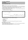
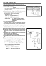
Wiring Connection
ECU Connector [A] ←→ Throttle Sensor Connector [B]
Y/W lead (ECU terminal 2)
BR/BK lead (ECU terminal 14)
If the wiring is good, check the ECU for its ground and
power supply (see ECU section).