


16-76 ELECTRICAL SYSTEM
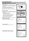
Switches and Sensors
•
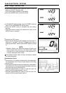
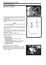
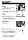
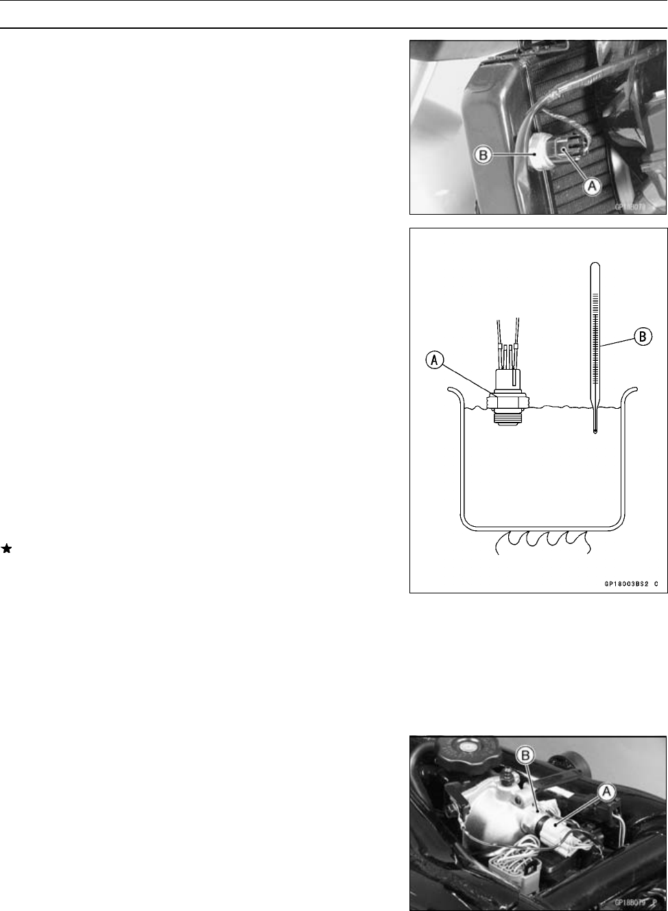
Disconnect the connector [A].
•
Remove the fan switch [B].
•
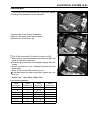
Suspend the switch [A] in a container of coolant so that
the t emperature–sensing projection and threaded portion
are submerged.
•
Suspend an accurate thermometer [B] in the coolant so
that the sensitive portions are located in almost the sam e
depth.
NOTE
○
The switch and thermometer must not touch the con-
tainer sides or bottom.
•
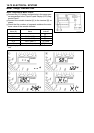
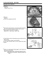
Place the container over a source of heat and gradu-
ally raise the temperature of the coolant while stirring the
c
oolant gently.
•
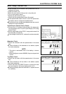
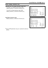
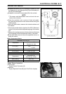
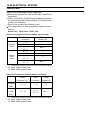
Using the hand tester, measure the internal resistance
of the switch across the terminals at the temperatures
shown in the table.
Special Tool - Hand Tester: 57001–1394
If the hand tester does not show the specified values, re-
place the switch.
Fan S witch Resistance
Rising temperature:
From OFF to ON a t 93 ∼ 103°C (199 ∼ 217°F)
Falling temperature:
Fan stops with the temperature 3 ∼ 8°C(38∼ 46 °F)
lower than the operation temperature range.
ON: Less than 0.5 Ω
OFF: More than 10 MΩ
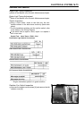
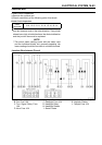
Water Temperature Sensor Inspection
•
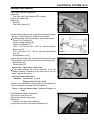
Remove the fuel tank (see Fuel System (DFI) chapter).
•
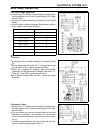
Disconnect the water temperature sensor connector [A].
•
Remove the water temperature sensor [B] (see Fuel Sys-
tem (DFI) chapter).