


3-84 FUEL SYSTEM (DFI)
Fuel Injectors
Injector Signal Test
•
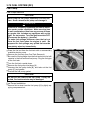
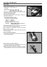
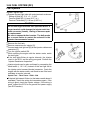
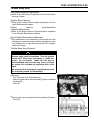
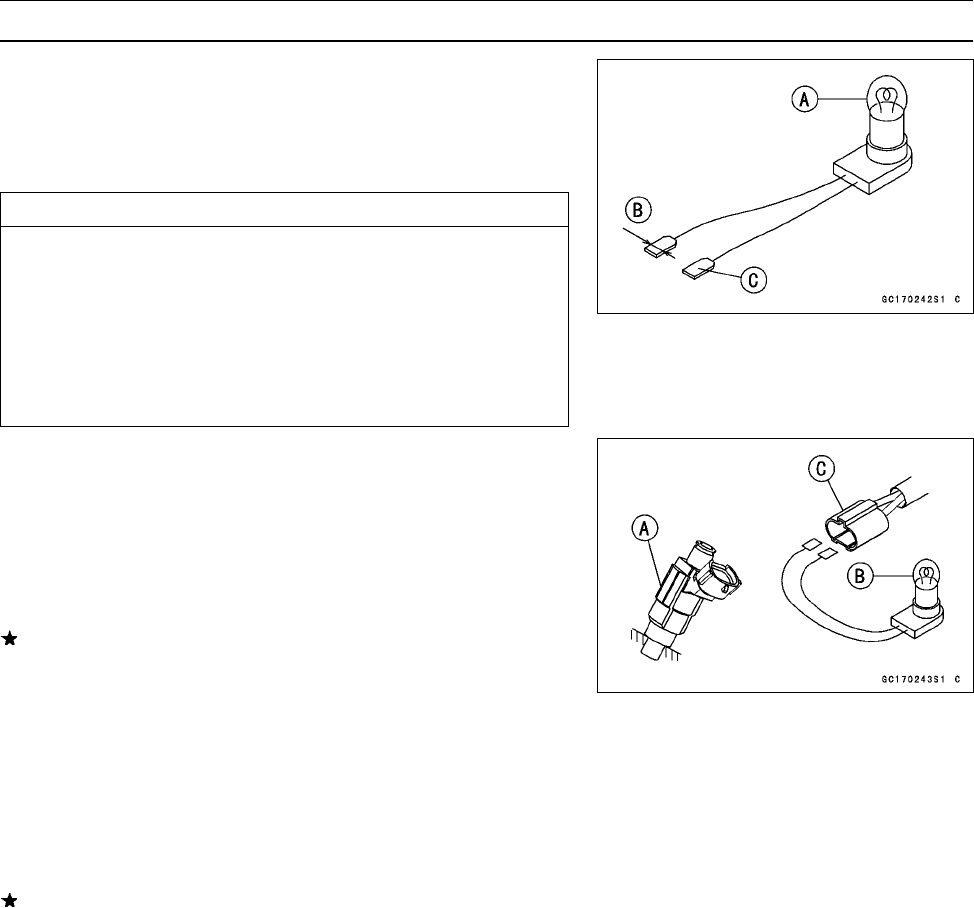
Prepare two test light sets with male terminals as shown.
Rating
of Bulb [A]: 12 V × 3 ∼ 3.4 W
Terminal Width [B]: 1.8 mm (0.071 in.)
Terminal Thickness [C]: 0.8 mm (0.031 in.)
CAUTION
Do not use larger terminals than specified above. A
larger
terminal could damage the injector main har-
ness connector (female), leading to harness repair
or replacement.
Be sure
to connect bulbs in series. The bulb w orks
as a current limiter to protect the solenoid in the
injector from excessive current.
•
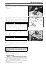
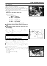
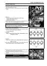
Remove the f uel t ank.
•
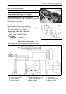
Remove connectors for injector [A].
•
Connect each test light set [B] to the injector subharness
connector [C].
•
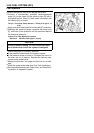
Turn the ignition switch ON.
•
While cranking the engine with the starter motor, watch
the test lights.
If the test lights flicker at regular intervals, the injector
circuit in the ECU, and the wiring are good. Perform the
“Injector Resistance Inspection”.
○
Injector signals can be also confirmed by connecting the
hand tester (× 10 V AC) instead of the test light set to
the injector main harness (female) connector. Crank the
engine with the starter motor, and check to see if the hand
oscillates at regular intervals.
Special Tool - Hand Tester: 57001–1394
If the test light doesn’t flicker (or the tester needle doesn’t
oscillates), check the wiring and connectors again. If the
wiring is good, check the injector voltage. If the wiring is
good, inspect the ECU for its ground and power supply
(see ECU section).