


CRANKSHAFT/TR ANSMISSION 9-17
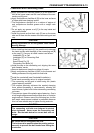
Crankshaft and Connecting Rods
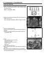
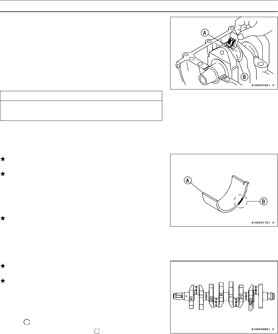
Connecting Rod Big End Bearing Insert/Crankpin
Wear
•
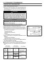
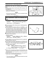
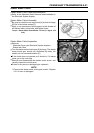
Measure the bearing insert/crankpin [B] clearance with
plastigage [A].
○
Tighten the big end nuts to the specified torque (see C on-
necting Rod Installation).
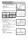
NOTE
○
Do not move the connecting rod and crankshaft during
clearance measurement.
CAUTION
After measurement, replace the connecting rod
bolts.
Connecting Rod Big End Bearing Insert/Crankpin Clearance
Standard: 0.041 ∼ 0.071 mm (0.0016 ∼ 0.0028 in.)
Service Limit: 0.11 mm (0.0043 in.)
If the clearance is within the standard, no bearing replace-
me
nt is required.
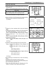
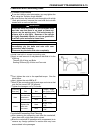
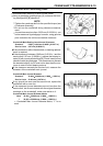
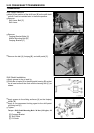
If the clearance is between 0.072 mm (0.00284 in.) and
the service limit (0.11 mm, 0.0043 in.), replace the bear-
in
g inserts [A] with inserts painted blue [B]. Check i n-
sert/crankpin clearance with the plastigage. The clear-
ance may exceed the standard slightly, but it must not be
l
ess than the minimum in order to avoid bearing seizure.
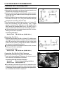
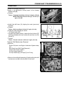
If the clearance exceeds the service limit, measure the
diameter of the crankpins.
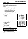
Crankpin Diameter
Standard: 34.984 ∼ 35.000 mm (1.3773 ∼ 1.3780 in.)
Service Limit: 34.97 mm (1.3768 in.)
If any crankpin has worn past the service limit, replace the
crankshaft with a new one.
If the measured crankpin diameters are not less than the
service limit, but do not coincide with the original diameter
markings on the crankshaft, make new marks on it.
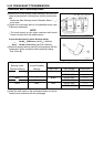
Crankpin Diameter Marks
None
34.984 ∼ 34.992 mm (1.3773 ∼ 1.3776 in.)
34.993 ∼ 35.000 mm (1.3777 ∼ 1.3780 in.)
∆: Crankpin Diameter Marks, " "ornomark.
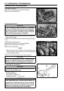
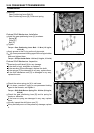
•
Measure the connecting rod big end inside diameter, and
mark each connecting rod big end in accordance with the
inside diameter.
•
Tighten the connecting r od big end nuts to the specified
torque (see Connecting Rod Installation).
NOTE
○
The mark already on the big end should almost coincide
with the measurement.