


16-32 ELECTRICAL SYSTEM
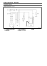
Chargi ng System
•
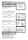
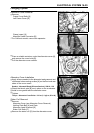
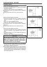
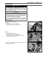
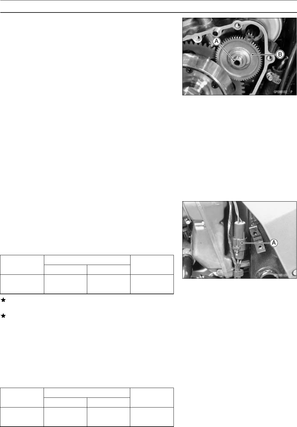
Apply a thin coat of molybdenum disulfide grease to the
shaft [A], and install it and starter idle gear [B].
•
Instal
l the alternator cover (see Alternator Cover Installa-
tion).
Alternator Inspection
There are three types of alternator failures: short, open
(wire burned out), or loss in rotor magnetism. A short or
open in one of the coil wires will result in either a low output,
or no output at all. A loss in rotor magnetism, which may be
caused by dropping or hitting the alternator, by leaving it
near an electromagnetic field, or just by aging, will result in
low output.
•
To check the alternator output voltage, do the following
procedures.
○
Turn off the ignition switch.
○
Remove the frame cover (see Alternator Cover Removal).
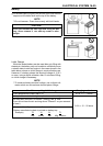
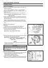
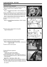
○
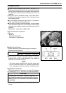
Disconnect the alternator lead connector [A].
○
Connect the hand tester as shown in the table 1.
○
Start the engine.
○
Run it at the rpm given in the table 1.
○
Note the voltage readings (total 3 measurements).
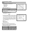
Table 1 Alternator Output Voltage
Tester Connections Reading
Range
Tester (+) to Tester (–) to @4,000rpm
250 V One Black Another 42 V or
AC
lead Black lead
more
If the output voltage shows the value in the table, the al-
ternator operates properly.
If the output voltage shows a much higher than the v alue
in the table, the regulator/rectifier is damaged. A much
lower reading than that given in the table indicates that
the alternator is defective.
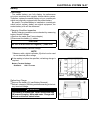
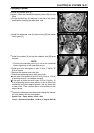
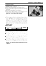
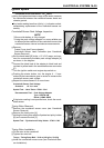
•
Check the stator coil resistance as follows.
○
Stop the engine.
○
Connect the hand tester as shown in the table 2.
○
Note the readings (total 3 measurement).
Table 2 Stator Coil Resistance
Tester
Connections
Range Tester (+) to Tester (–) to
Reading
One Black
Another
×1Ω
lead Black lead
0.3 ∼ 0.4 Ω