


9-18 CRANKSHAFT/T RANSMISSION
Crankshaft and Connecting Rods
Connecting Rod Big End I nside Diameter Marks
None
38.000mm ∼ 38.008mm (1.4961 ∼ 1.4964 in.)
38.009 ∼ 38.016 mm (1.4964 ∼ 1.4967 in.)
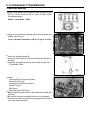
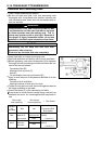
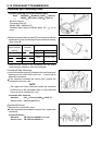
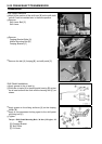
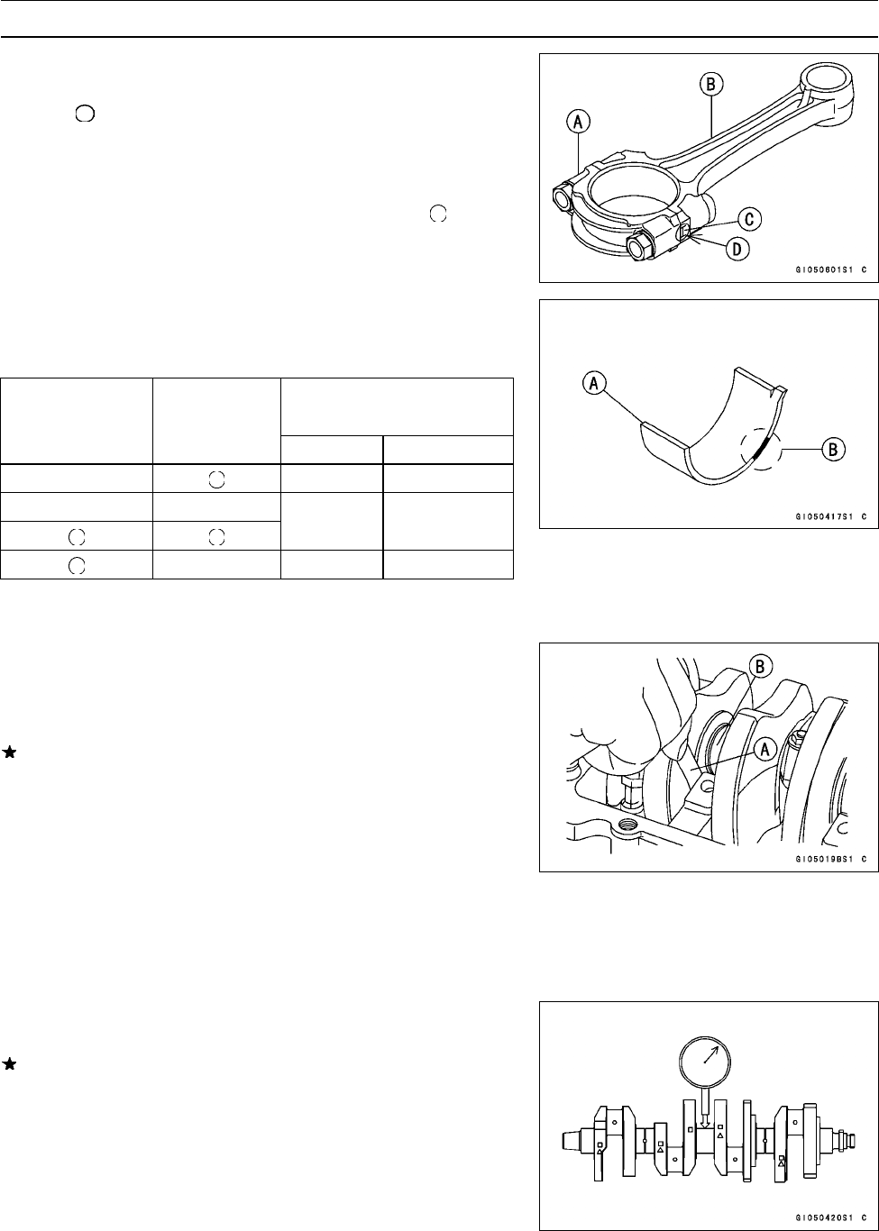
BigEndCap[A]
Connecting Rod [B]
Weight Mark, Alphabet [C]
Diameter Mark (Around Weight Mark) [D]: “
”orno
mark
•
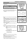
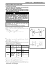
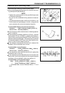
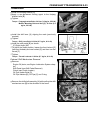
Select the proper bearing insert [A] in accordance with the
combination of the connecting rod and crankshaft coding.
Size Color [B]
Co
n-rod Big End
Cr
ankpin
Bearing Insert
Inside Diameter Diameter
Marking Marking
S
ize Color
Part Number
None Brown 92139–1110
None None
Black 92139–1109
None Blue 92139–1108
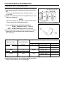
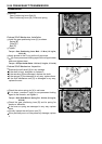
•
Install the new inserts in the connecting rod and check
insert/crankpin clearance with the plastigage.
Crankshaft Side Clearance
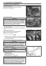
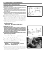
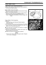
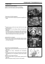
•
Insert a thickness gauge [A] between the crankcase main
bearing and the crank web at the No. 2 journal [B] to
determine clearance.
If the clearance exceeds the service limit, replace t he
crankcase halves as a set.
NOTE
○
The upper and lower crankcase halves are machined
at the factory in the assembled state, so the crankcase
halves must be replaced as a set.
Crankshaft Side Clearance
Standard: 0.05 ∼ 0.20 mm (0.0020 ∼ 0.0079 in.)
Service Limit: 0.40 mm (0.0157 in.)
Crankshaft Runout
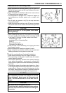
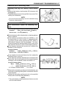
•
Measure the crankshaft r unout.
If the measurement exceeds the service limit, replace the
crankshaft.
Crankshaft Runout
Standard: TIR 0.02 mm (0.0008 in.) or less
Service Limit: TIR 0.05 mm (0.0020 in.)