


ELECTRICAL SYSTEM 16-71
Meter, Gauge, Indic ator Unit
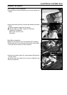
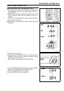
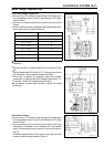
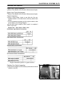
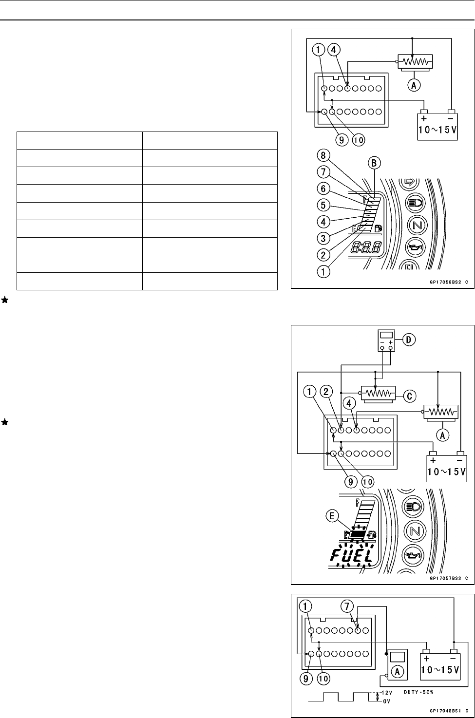
Fuel Level Gauge Inspection:
•
Connect the 12 V battery and terminals in the same man-
ner as specified in the “Liquid Crystal Display (LCD) Seg-
ments Check”.
•
Connect a variable rheostat [A] to terminal [4] and [9] as
shown.
•
Check that the num ber of segment [B] matches the resis-
tance value of the variable rheostat.
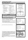
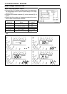
Resistance (Ω) Number of Segments
0 ∼ 16.5 F8
11.5 ∼ 28.5 7
21.5 ∼ 40.5 6
31.5 ∼ 52.5 5
41.5 ∼ 64.5 4
51.5 ∼ 76.5 3
61.5 ∼ 88.5 2
71.5 ∼ above E1
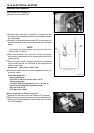
If this display function does not work, replace the meter
assembly.
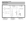
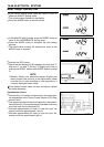
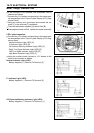
•
Connect an other variable rheostat [C] to terminal [2] and
[9].
•
Set the hand tester [D] to the DC 10 V range and connect
it to terminals of the variable rheostat as shown.
•
When the 1 segment [E] appears, adjust the variable
rheostat [C] so that the terminal voltage is less than 5.7 V.
○
Then the 1 and FUEL segments should flush.
If this display function does not flush, replace the meter
assembly.
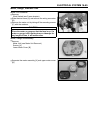
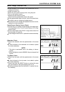
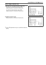
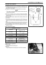
Tachometer C heck:
•
Connect the 12 V battery and terminals in the same man-
ner as specified in the "Liquid Crystal Display (LCD) Seg-
ments Check".
•
The revolutions per minute (rpm) equivalent to the input
frequency is indicated in the oscillator [A] if the square
wave (illustrated as shown) would be i nput into the termi-
nal [7].
○
Indicates approximately 6 000 rpm in case the input fre-
quency would be approximately 200 Hz.