


2-18 PERIODIC MAINTENANCE
Periodic Maintenance Procedures
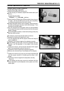
•
Back out the same number of turns counted when first
turned in. This is to set the screw to its original position.
NOTE
○
A throttle body has different “turns out” of the bypass
screw for each individual unit. When setting the bypass
screw, use the “turns out” determined during disassem-
bly. Use t he specifications in this manual only if the orig-
inal number is unknown.
•
Repeat the same procedure for other bypass screws.
•
Repeat the synchronization.
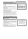
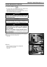
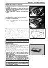
If the vacuums are correct, check the output voltage of
the main throttle sensor (see Output Voltage Inspection of
Main Throttle Sensor in the Fuel System (DFI) chapter).
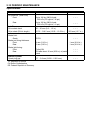
Main Throttle Sensor Output Voltage
Connections to ECU
Meter (+) → Y/W lead (terminal 2)
Meter (–) → BR/BK lead (terminal 14)
Standard:
0.99 ∼ 1 .03 V DC (at idle throttle opening)
If the output voltage is out of the range, check the throttle
input voltage (see Input Voltage Inspection of Main Throt-
tle Sensor in the Fuel System (DFI) chapter).
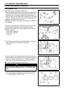
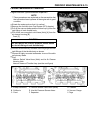
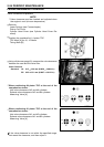
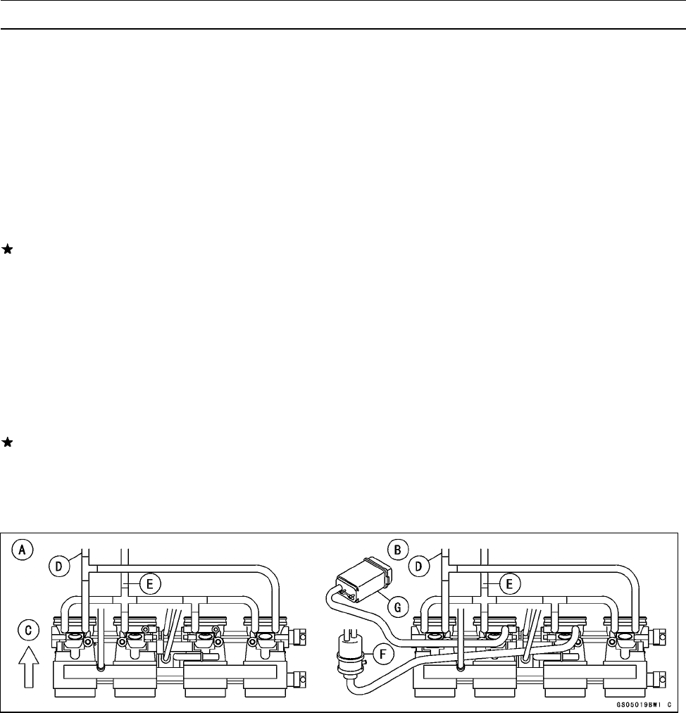
•
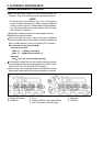
Remove the vacuum gauge hoses and install the vacuum
hoses and rubber caps on the original position as shown.
A. Except California C. Front F. Separator
B. California D. Vacuum Switch Valve Hose (small) G. Canister
E. Inlet Air Pressure S ensor Hose