


9-16 CRANKSHAFT/T RANSMISSION
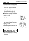
Crankshaft and Connecting Rods
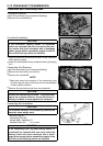
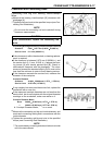
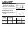
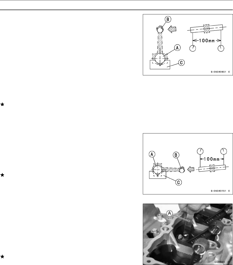
Connecting Rod Bend
•
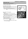
Remove the connecting rod big end bearing inserts, and
reinst
all the connecting rod big end cap.
•
Select an arbor [A] of the same diameter as the connect-
ing rod big end, and insert the arbor through the connect-
ing ro
d big end.
•
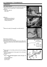
Select an arbor of the same diameter as the piston pin and
more than 105 m m (4.13 in.) long, and insert the arbor [B]
thro
ugh the c onnecting rod small end.
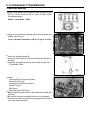
•
On a surface plate, set the big-end arbor on V blocks [C].
•
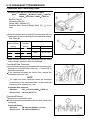
With the connecting rod held vertically, use a height
gaug
e to measure the difference in the height of the
arbor above the surface plate over a 100 mm (3.94 in.)
length to determine the amount of connecting rod bend.
If c
onnecting rod bend exceeds the service limit, the con-
necting rod must be replaced.
Connecting Rod Bend
Service Limit: TIR 0.2/100 mm (0.008/3.94 in.)
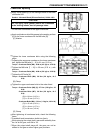
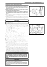
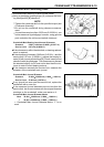
Connecting Rod Twist
•
With the big-end arbor [A] still on V block [C], hold the con-
necting rod horizontally and measure the amount that the
arbor [B] varies from being parallel with the surface plate
over a 100 mm (3.94 in.) length of the arbor to determine
the amount of connecting rod twist.
If connecting rod twist exceeds the service limit, the con-
necting rod must be replaced.
Connecting Rod Twist
Service Limit: TIR 0.2/100 mm (0.008/3.94 in.)
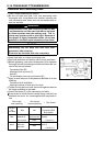
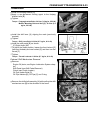
Connecting Rod Big End Side Clearance
•
Measure connecting rod big end side clearance.
○
Insert a thickness gauge [A] between the big end and ei-
ther crank web to determine clearance.
Connecting Rod Big End Side Clearance
Standard: 0.13 ∼ 0.38 mm (0.0051 ∼ 0.0150 in.)
Service Limit: 0.58 mm (0.023 in.)
If the clearance exceeds the service limit, replace the con-
necting rod with new one and then check clearance again.
If clearance is too large after connecting rod replacement,
the crankshaft also must be replaced.