


3-44 FUEL SYSTEM (DFI)
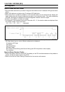
Inlet Air Pressure Sensor (Service Code 12)
Output Voltage Inspection
NOTE
○
The output voltage changes according to the local at-
mospheric pressure.
•
Measure the output voltage at the ECU in the same way
as input voltage inspection. Note the following.
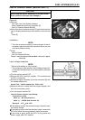
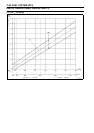
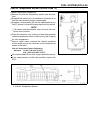
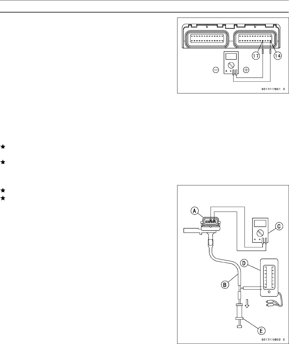
Inlet Air Pressure Sensor Output Voltage
Connections to ECU
Meter
(+) → Y/BL lead (terminal 17)
Meter (–) → BR/BK lead (terminal 14)
Usable Range:
3.74 ∼ 4.26 V DC at the standard
atmospheric pressure (101.32 kPa,
76 cmHg abs.)
•
Turn the i gnition switch OFF.
If the output voltage is within the usable range, check the
ECU for its ground, and power supply (see this chapter).
If the output voltage is out of the usable range, remove
the fuel tank and check t he wiring. If the output voltage is
4.8 V, the ECU is normal.
If the wiring is good, check the sensor for various vacuum.
If the output voltage for various vacuum is normal check
the ECU for its ground, and power supply (see ECU sec-
tion).
•
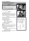
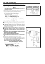
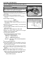
Remove the i nlet air pressure sensor [A] and disconnect
the vacuum hose from the sensor.
○
Do not disconnect the sensor connector.
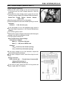
•
Connect an auxiliary hose [B] to the inlet air pressure sen-
sor.
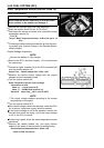
•
Temporarily install the inlet air pressure sensor.
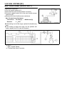
○
Connect a commercially available digital meter [C], vac-
uum gauge [D], the fork oil level gauge [E] and the har-
ness adapter to the inlet air pressure sensor.
Special Tools - Fork Oil Level Gauge: 57001–1290
Sensor Harness Adapter: 57001–1561
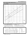
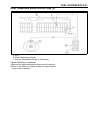
Inlet Air Pressure Sensor Output Voltage
Connection to Adapter
Meter (+) → BL (sensor Y/BL) lea d
Meter (–) → Y/W (sensor BR/BK) lead