


16-38 ELECTRICAL SYSTEM
Ignition System
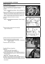
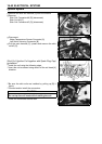
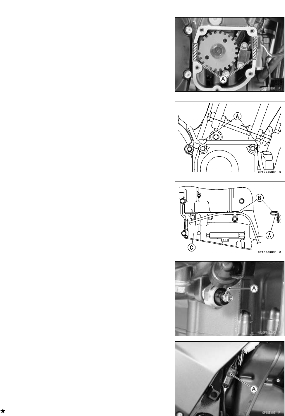
Crankshaft Sensor Installation
•
Route the crankshaft sensor lead correctly (see Cable,
Wire, a
nd Hose Routing in Appendix chapter).
•
Tighten:
Torque - Crankshaft Sensor Bolts: 5.9 N·m (0.6 kgf·m, 53
in·lb)
•
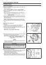
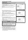
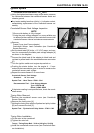
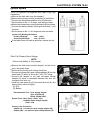
Apply silicone sealant [A] to the crankshaft sensor lead
grommet and crankcase halves mating surface on the
front and rear sides of the crankshaft sensor cover mount.
Sealant - Kawasaki Bond (Silicone Sealant): 56019–120
•
Install the clamps [A] direction as shown.
•
Tighten:
Torque - Crankshaft Sensor Cover B olts: 11 N·m (1.1 kgf·m,
95 in·lb)
•
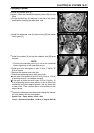
Hold the sensor lead [A] with the clamp [B].
Upper Crankcase [C]
•
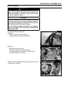
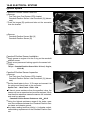
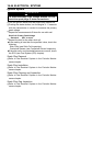
Install oil pressure switch lead terminal [A] securely.
○
Install the lead terminal direction upward.
Torque - Oil Pressure Switch Terminal Bolt: 1.5 N·m (0.15
kgf·m, 13 in·lb)
•
Install t he other removed parts.
Crankshaft Sensor Inspection
•
Remove:
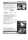
Frame Cover (see Frame chapter)
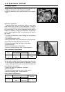
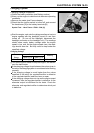
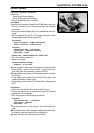
Crankshaft Sensor Lead Connector [A]
•
Set the hand tester to the × 100 Ω range and connect (+)
lead to the yellow/black lead and (–) lead to the black lead
in the connector.
Special Tool - Hand Tester: 57001– 1394
If there is more resistance than the specified value, the
coil has an open lead and must be replaced. Much less
than this resistance means the coil is shorted, and must
be replaced.