


ELECTRICAL SYSTEM 16-45
Ignition System
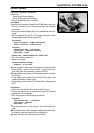
Interlock Operation Inspection
•
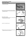
Remove:
Seats (see Frame chapter)
Junction Box (see this chapter)
○
Do not disconnect the connectors.
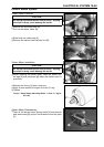
1st Check
•
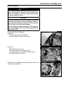
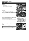
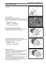
Measure the terminal voltage of the G/BK lead in the junc-
tion box connector [A] in accordance w ith the following
procedure.
○
Insert the needle adapter [B] in the Green/Black lead ter-
minal.
○
Set the tester [C] to the 25 V DC range, connect it to the
needle adapter and frame ground [D].
Connection:
Tester (+) Terminal → G/BK Lead Terminal
Tester (–) Terminal → Frame Ground
Condition:
Transmission Gear → 1st Position
Clutch Lever → Release or Pulled In
Side Stand → Down
Special Tool - Needle Adapter Set: 57001–1457
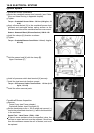
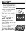
○
Turn the ignition switch on.
○
Read the voltage.
Interlock Operation Voltage
Standard:
4Vormore
If the voltage is lower than the standard, inspect the side
stand switch, starter lockout switch, and junction box.
And their parts are normality, replace the ECU.
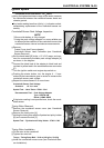
If the voltage is standard, push the starter button to check
as follows.
○
If the starter motor does not turn, the ECU is good, and
check the starter system circuit.
○
If the starter motor turned, ECU is defective. Replace the
ECU.
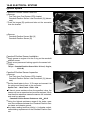
2nd Check
Raise the rear wheel off the ground with a stand.
•
Inspect the engine for its secure stop after the following
operations are completed.
•
Run the engine to the following conditions.
Condition:
Transmission Gear → 1st Position
Clutch Lever → Release
Side Stand → Up
•
Set the side stand on the ground, then the engine will
stop.
If whichever may not be stopped, inspect the starter lock-
out switch, side stand switch and junction box.
If their parts are normality, replace the ECU.