


16-80 ELECTRICAL SYSTEM
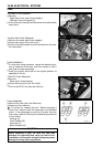
Switches and Sensors
•
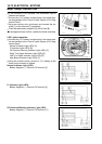
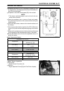
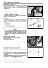
Connect the test light [A] (12 V 3.4 W bulb a socket with
leads) and the 12 V battery [B] to the fuel level s ensor
connec
tor [C].
Connections:
Battery (+) → 12 V 3.4 W Bulb (one side)
12 V 3.4 W Bulb (other side) → Blue Lead Terminal
Battery (–) → BK/Y Lead Terminal
If the test light turn on, the reverse switch is defective.
Replace the fuel level sensor.
•
Remove:
Fuel Level Sensor (see Fuel Level Sensor Inspection)
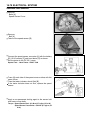
•
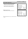
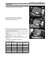
Connect the test light (12 V 3.4 W bulb in a socket with
leads) and the 12 V battery to the fuel pump connector as
shown.
12 V Battery [A]
Test Light [B]
Fuel Pump Connector [C]
FuelReserveSwitch[D]
If the test light doesn’t light, replace the fuel level sensor.
NOTE
○
It may take a long time to turn on the t est light in case
that the fuel reserve switch is inspected just after the
fuel level sensor is removed. Leave the fuel reserve
switch with leads for inspection connected for ten (10)
minute.
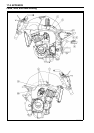
Diode (Rectifier) Inspection
•
Remove the fairing (see Frame chapter)
•
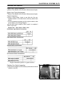
Cut the vinyl tape.
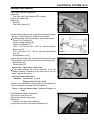
•
Disconnect the diode [A].
•
Set the hand tester to the × 100 Ω range.
Special Tool - Hand Tester: 57001–1394
•
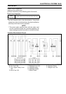
Check the continuity between the diode terminals in both
directions.
If there is continuity in one direction (forward direction) but
no continuity (infinity) in the reverse direction, the diode
is normal.
The diode is defective if there is continuity after changing
the direction, or it if remains with no continuity.
NOTE
○
The actual resistance measurement in the forward
direction varies with the tester used and the individual
diodes. Generally speaking, it is acceptable if the
tester ’s indicator swings approximately halfway.