


ELECTRICAL SYSTEM 16-39
Ignition System
Crankshaft Sensor Resistance: 375 ∼ 565 Ω
•
Using the highest resistance range of the tester, measure
the resistance between the crankshaft sensor leads and
chassis ground.
Any tester reading less than infinity (∞) indicates a short,
necessitating replacement of the crankshaft sensor as-
sembly.
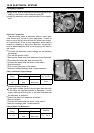
Crankshaft Sensor Peak Voltage Inspection
NOTE
○
Be sure the battery is fully charged.
○
Using the peak voltage adapter is a more reliable way
to determine the condition of the crankshaft sensor than
crankshaft sensor internal resistance m easurements.
•
Remove:
Frame Cover (see Frame chapter)
Crankshaft Sensor Lead Connector (see Crankshaft
Sensor Removal)
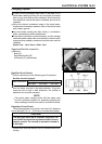
•
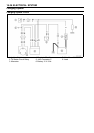
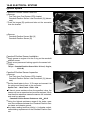
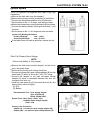
Set the hand tester [B] to the × 10 V DC range, and con-
nect it a commercially available peak voltage adapter [A]
as shown in the diagram.
•
Connect the black lead of the adapter to black lead and
red lead to yellow lead in the crankshaft sensor connector
[C].
•
T urn the ignition switch and engine stop switch on.
•
Pushing the starter button, turn the engine 4 ∼ 5sec-
onds with the transmission gear in neutral to measure the
crankshaft sensor peak voltage.
•
Repeat the m easurement 5 or m ore times.
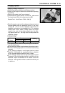
Crankshaft Sensor Peak Voltage
Standard:
1.9 V or more
Special Tool - Hand Tester: 57001–1394
Recommended Tool- Peak Voltage Adapter
Type: KEK-54-9-B
Brand: KOWA SEIKI
If the tester reading is not specified one, check the crank-
shaft sensor.
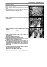
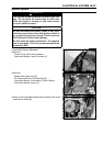
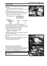
Timing Rotor Removal
•
Remove the crankshaft sensor cover (see Crankshaft
Sensor Removal)
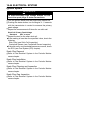
•
Remove the timing rotor [A].
○
Holding the timing rotor with the flywheel and pulley holder
[B] and unscrew the bolt [C].
Special Tool - Flywheel and Pulley Holder : 57001–1343
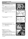
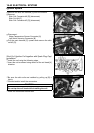
Timing Rotor Installation
•
Fit the rotor to the crankshaft.
•
Tighten the rotor bolt.
Torque - Timing Rotor Bolt : 39 N·m (4.0 kgf·m, 29 ft·lb)
•
Install the crankshaft sensor cover ( see Crankshaft Sen-
sor Installation).