


16-66 ELECTRICAL SYSTEM
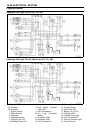
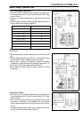
Meter, Gauge, Indicator Unit
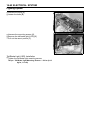
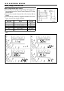
Electro nic Combination Meter Unit Inspection
•
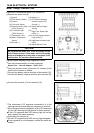
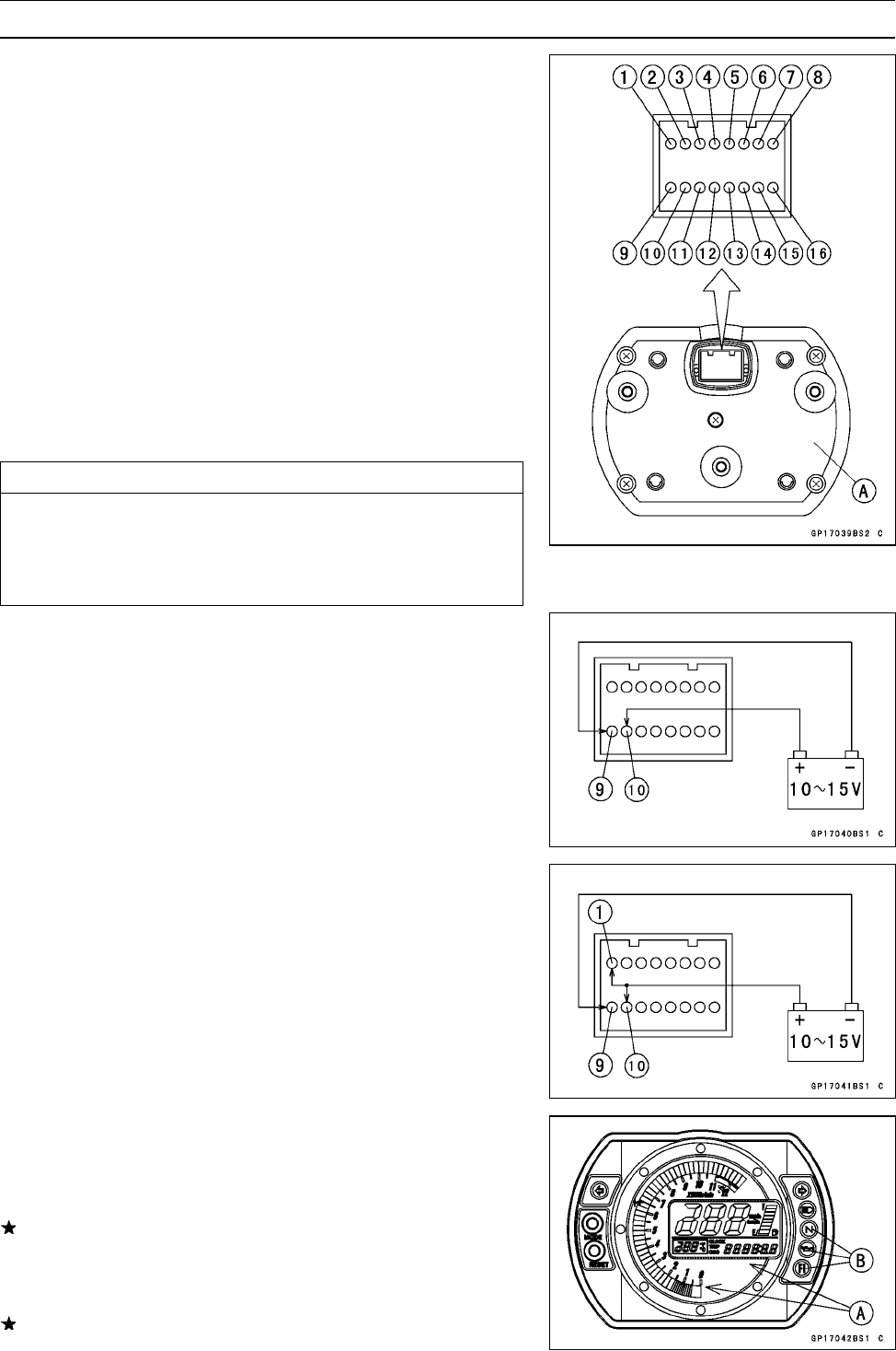
Remove the meter unit [A].
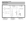
[1] Ignition [10]
Battery (+)
[2]
Fuel Reserve Switch
[11]
Oil Pressure Warning
[3] Unused
Indicator Light (LED)
[4]
Fuel Level Sensor Ground (–)
[5] Neutral Indicator Light [12] Speed Sensor Supply
(LED) Ground (–)
Voltage
[6] FI Indicator Light [13]
Right Turn Signal Light
(LED) Ground (–) (LED) (+)
[7] Tachometer Pulse [14]
Left Turn Signal Indicator
[8] Water Temperature
Lig
ht (LED) (+)
Sensor
[15] High Beam Indicator Light
[9] Ground (–) (LED)
[16]
Speed Sensor Pulse
CAUTION
Do not drop the meter unit. Place the meter unit so
that it faces upward. If the m eter unit is left upside
down or sideways for a long time or dropped, it w ill
malfunction. Do not short each terminals.
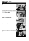
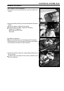
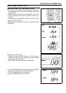
Liquid Crystal Display (LCD) Segments Check:
•
Use t he harness adapter for meter inspection.
Special Tool - Harness Adapter : 57001–1542
•
Using the auxiliary wires, connect the 12 V battery to the
meter unit connector as follows.
○
Connect the battery positive terminal to the terminal [10].
○
Connect the battery negative terminal to the terminal [9].
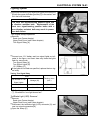
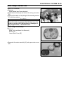
•
Connect the terminal [1] to the terminal [10].
○
The tachometer LCD segments momentarily to it last
readings two times and segment movement is reversal.
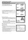
○
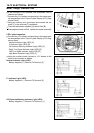
When the terminals are connected, all the LCD segments
[A] and LED warning light [B] appear for three seconds.
If the LCD segments and LED warning light will not ap-
pear, r eplace the meter assembly.
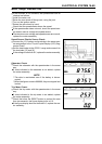
•
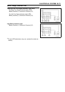
Disconnect the terminal [1].
○
All the LCD segments and LED warning light disappear.
If the segments do not disappear, replace the meter as-
sembly.