


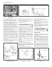
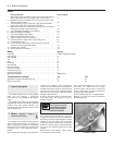
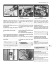
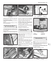

8 Withdraw the solenoid and yoke off the
armature and from the drive end bracket.
Note the steel and fibre washers and the
shims on the armature shaft (photo).
9 Extract the split pin and tap out the
engagement lever pivot pin.
10 Pull the rubber packing piece from the
drive end bracket.
11 Withdraw the armature with solenoid
plunger, coil spring and engagement lever.
12 Clean the commutator with a fuel soaked
rag or very fine glass paper. Do not undercut
the mica insulators on the commutator.
Drive
13 To remove the drive assembly from the
armature shaft, use a piece of tubing to tap
the stop collar down the shaft to expose the
snap ring. Remove the snap ring and stop
collar and slide the drive assembly from the
shaft.
14 Refitting is a reversal of removal, but use a
new snap ring to secure the drive to the
armature shaft.
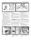
10 Fuses and relays
1
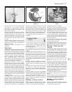
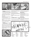
1 The fuse box is located under the left-hand
side of the facia panel and is held in place by
two hand screws (photo).
2 The fuses and the circuits protected are
identified by symbols. Refer also to Specifi-
cations.
3 If a fuse blows, always renew it with one of
identical rating. If the new fuse blows
immediately, find the cause before renewing
the fuse for the second time. This is usually
due to defective wiring insulation causing a
short circuit.
4 Never substitute a piece of wire or other
makeshift device for a proper fuse.
5 Various relays are plugged into the fuse
block and include those for the heated rear
screen, heater and horns.
6 On cars fitted with power-operated front
windows and centralised door locking, the
fuses and relays for these circuits are
mounted separately under the right-hand side
of the facia panel.
7 The relay (flasher unit) for the direction
indicators and hazard warning lamps is
located on the lower part of the
steering column combination switch and
is accessible after removing the column
shroud.
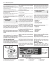
11 Steering column
combination switch
1
1 Disconnect the battery negative lead.
2 Remove the steering column shrouds.
3 The switch can be removed without
having to take off the steering wheel, but for
clarity, the photographs show the wheel
removed.
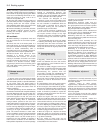
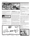
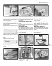
4 Unscrew the switch clamp nuts, disconnect
the wiring plug and remove the switch from
the steering column (photo).
5 Refitting is a reversal of removal, but make
sure that the activating projections on the
steering wheel hub engage correctly with the
switches.
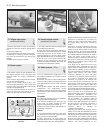
12 Courtesy lamp switch
1
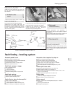
1 These are located in and secured to the
body pillars with a single screw (photo).
2 Disconnect the battery negative lead.
3 Extract the switch screw and withdraw the
switch.
4 If the leads are to be disconnected, tape
them to the pillar to prevent them from
slipping inside.
5 Refitting is a reversal of removal. Apply
petroleum jelly to the switch contacts to
prevent corrosion.
13 Rocker and push-button
switches
1
1 These are mounted in panels on each side
of the instrument panel.
2 Disconnect the battery negative lead.
3 Prise off the instrument panel hood cover.
This is held in place by clips. The careful use
of a screwdriver will assist in releasing them
(see Section 21).
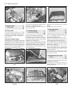
4 Extract the switch panel fixing screws.
These compress spring clips which in turn
secure the switch panel (photo).
5 Withdraw the switch panel until the wiring
plugs can be disconnected. Record the
location of the plugs before disconnecting
Electrical system 9•5
11.4 Unscrewing steering column switch
clamp nut
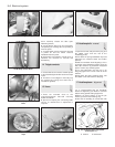
1 Direction indicator flasher unit (relay)
10.1 Fuse block (later models)
1 Horn relay
2 Heated tailgate window relay
9.8 Starter motor dismantled
13.4 Switch panel screw12.1 Courtesy lamp switch
9