


protective shield to gain access to the pump
which is located forward of the fuel tank.
60 Disconnect the fuel hoses and the wiring
connector, release the retaining clamp and
withdraw the pump unit.
Refitting all components
61 Refitting of all components is a reversal of
the removal procedure, but note the following
specific points.
62 Ensure that all components are clean prior
to refitting and where applicable, use new
seals and gaskets. Ensure that all connections
are securely and correctly made.
63 Do not reconnect the battery until all the
refitting procedures are complete.
64 When the engine is restarted, check
around the fuel injection system for any signs
of leakage from the fuel supply and return
components.
Lambda sensor - general
65 The sensor is screwed into the exhaust in
front of the catalytic converter.
66 A faulty sensor can damage the converter,
therefore it must be checked regularly (see
Maintenance schedule, Section 3) by a dealer
using special equipment.
67 Use of leaded fuel will also damage this
sensor, as well the converter.
PART F:
TURBOCHARGER SYSTEM
Description
1 A turbocharger is fitted to certain 1301 and
1372 cc ie engines. The accompanying
photographs are all taken from a 1301 cc
engine, but the system is much the same for
both engine types.
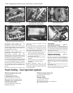
2 The turbocharger is basically a shaft with an
exhaust gas-driven turbine at one end, and a
compressor located at the other end which
draws in outside air and forces it into the inlet
manifold. By compressing the incoming air, a
larger charge can be let into each cylinder,
and greater power output is achieved than
with normal aspiration.
3 Lubrication of the turbocharger shaft
bearings is provided by pressurised engine
oil, and the unit is cooled by the coolant from
the engine cooling system.
4 A wastegate valve is incorporated in the
turbocharger to divert excessive exhaust gas
pressure from the turbine into the exhaust
pipe at a predetermined pressure level.
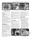
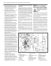
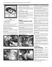
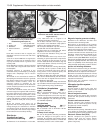
5 A maximum air pressure switch is located in
the inlet manifold. Its purpose is to cut the
ignition system off when the turbocharger
system pressure continues to increase
beyond 0.86 bars (12.5 lbf/in
2
). This would
otherwise damage the engine, due to high
combustion temperatures and pressures
(photo).
6 An intercooler (heat exchanger) is located
between the turbocharger and the inlet
manifold. Its function is to cool the inlet
charge, thus increasing its density, to provide
greater power output.
7 A mechanical bypass valve is located
between the low-pressure pipe (downstream)
and the high-pressure pipe (upstream), which
reduces the inherent noise from the
turbocharger when the accelerator pedal is
released (photo).
8 None of the components of the
turbocharger system can be repaired and
parts are not available. Any fault will therefore
mean that the turbocharger or associated
assemblies will have to be renewed complete.
Precautions
9 The following precautions should be
observed when using a turbocharged vehicle.
a) Never operate the engine without the air
cleaner fitted.
b) Never switch off the engine before its
speed has dropped to idling. If the car
has been driven hard, allow it to idle for a
few minutes before switching off. Failure
to observe these recommendations can
cause damage to the turbocharger due to
lack of lubrication.
10 Always keep the fuel injection system
well-maintained and tuned. Operating on a
weak mixture can cause overheating of the
turbocharger.
Turbocharger
(1301 cc ie engine) -
removal and refitting ¡
11 Disconnect and remove the airflow meter
as described in Section 9C.
12 Disconnect the spiral-wound hose from
the fuel injector cooling duct.
13 Remove the turbocharger air hoses from
within the left-hand side of the engine
compartment. Note particularly their routing.
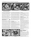
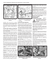
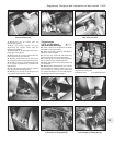
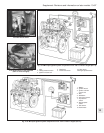
14 Remove the throttle housing/inlet
manifold as described in Section 9C, also the
fuel rail, injectors and inlet manifold branch
pipe stubs. Remove the alternator heat shield
(photo).
15 Remove the exhaust heat shield.
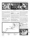
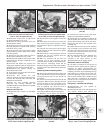
16 Unscrew the turbocharger-to-exhaust
pipe flange nuts (photos).
13•82 Supplement: Revisions and information on later models
9F.16A Turbocharger-to-exhaust flange
nut (arrowed)
9F.14 Alternator heat shield
9F.7 Bypass valve9F.5 Maximum air pressure switch
(arrowed)
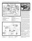
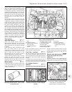
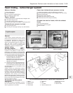
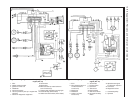
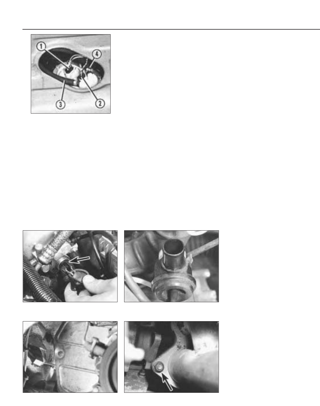
Fig. 13.63 Fuel pump and sender unit
location on the 1372 cc Turbo ie engine
(Sec 9E)
1 Fuel level gauge sender connector
2 Fuel pump connector
3 Fuel return hose
4 Fuel supply hose