


3 The centralised door locking system can
operate independently of the key.
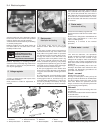
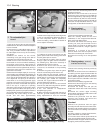
4 To gain access to the lock solenoid and
linkage, remove the front door trim panel as
described in Chapter 12.
5 Disconnect the battery negative lead.
6 Disconnect the electrical wiring plugs from
the solenoid within the door cavity.
7 Disconnect the solenoid from the lock lever
by removing the clip.
8 Unscrew the two bolts which secure the
solenoid to the door and remove it.
9 Renew the solenoid or switch as necessary.
10 Refitting is a reversal of removal.
11 Refer to Section 10 for details of system
fuses and relays.
33 Economy gauge
(Econometer)
2
1 This device is fitted to ES (energy saving)
models and indicates to the driver the fuel
consumption (in litres per 100 km) coupled
with a needle which moves over coloured
sections of a dial to make the driver aware
that his method of driving is either conducive
to high or low fuel consumption. Refer to
Chapter 3, Section 16.
2 The device is essentially a vacuum gauge
which also incorporates a warning lamp to
indicate to the driver when a change of gear is
required.
3 A fuel cut-out valve (see Chapter 3, Sec-
tion 11) is used in conjunction with the
economy gauge so that when the accelerator
pedal is released during a pre-determined
engine speed range, fuel supply to the engine
is stopped, but resumes when the engine
speed falls below the specified range.
LED (light emitter diode)
4 The gearchange indicator will only light up
at engine speeds in excess of 2000 rev/min
for vacuum pressures up to 600 mm Hg in 1st,
2nd and 3rd speed gears and for vacuum
pressures up to 676 mm Hg in 4th speed
gear. The light will not come on if 5th speed
gear is engaged or if the coolant temperature
is below 55ºC.
5 There is a two second delay in the light
coming on to prevent it operating during rapid
acceleration in a low gear.
6 If the LED light comes on during
deceleration it should be ignored.
Fault finding
7 A faulty economy gauge should be checked
in the following way.
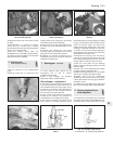
8 Refer to Section 21 and remove the
instrument panel.
9 Disconnect the economy gauge L
connector and then connect a test lamp
between the BN cable contact and earth. If
the lamp comes on then the gauge supply
circuit is not open. If the lamp does not come
on, check all connections in the supply cable
which comes from the interconnecting unit of
the electrical system, also Fuse No 12.
10 Now connect a voltmeter between the
white cable and earth. Check the voltage with
the engine not running, but the ignition
switched on. It should be between 0.7 and
0.9 volt. If the reading varies considerably
from that specified, check the connections
between the economy gauge and the fuel
cut-out device control unit. If the fault cannot
be rectified, renew the ignition control unit
(Digiplex system, see Chapter 4).
11 Now check the closed throttle valve plate
switch by connecting a voltmeter between the
brown and BN cables of the L connector. With
the valve plate open, there should be no
reading, but with it open, voltage should be
indicated.
12 Failure to conform as described will be
due to a faulty earth in the switch or a faulty
fuel cut-out device control unit.
13 A further test of the throttle valve plate
switch may be carried out by disconnecting
the multi-plug from the fuel cut-out device
control unit.
14 Connect a test lamp to contact 4 (positive
battery terminal). The lamp should come on,
when the engine is idling or the accelerator
released. If it does not, renew the throttle
valve plate switch.
15 Connect a tachometer to the brown/white
cable contact in the L connector and record
the engine speed with the engine running. If
no reading is obtained, renew the Digiplex
ignition control unit which must be faulty.
34 Check control (warning
module) system
2
1 This is fitted into the instrument panel of
certain models to provide a means of
checking the operation of many electrical
circuits and other systems in the interest of
safety. Sensors are used where appropriate.
2 The following components are not
monitored by the system, but have separate
warning lamps:
Handbrake “on”
Choke in use
Low engine oil pressure
Battery charge indicator
3 The multi-functional electronic device
automatically checks the following functions
whether the engine is running or not:
Coolant level
Disc pad wear
Door closure
Engine oil level
Front parking lamps
Rear foglamps
Stop lamps
4 The check information is stored by the
system monitor until the engine is started
when the display panel then indicates the
situation by means of the LEDs (light emitter
diodes) and the general lamp.
5 If all functions are in order, the green panel
lamp will come on when the ignition key is
turned and will go out after two to three
seconds.
6 If some functions are not in order, then the
red panel lamp will come on also the
appropriate LED.
Sensors - checking
7 If a fault signal occurs which is
subsequently found to be incorrect, first
check the wiring connections between the
9•12 Electrical system
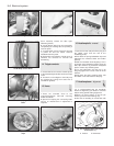
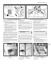
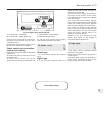
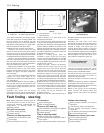
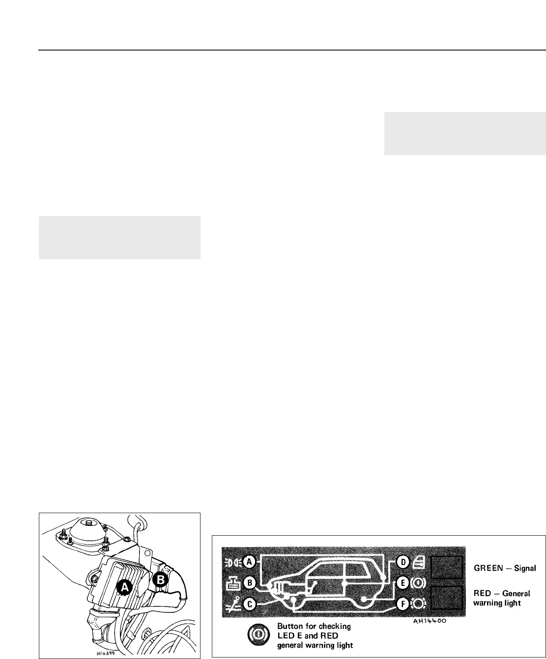
Fig. 9.15 Check system control panel (Sec 34)
A Parking lamps
B Coolant level
C Engine oil level
D Door closure
E Brake fluid level
F Disc pad wear
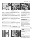
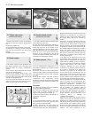
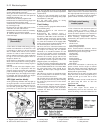
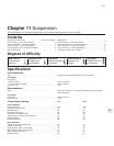
Fig. 9.14 Location of control units (Sec 33)
A Digiplex ignition system control unit
B Fuel cut-out valve control unit