


Idle speed and mixture
adjustment ¢
29 Before carrying out any adjustments, the
engine must be at operating temperature, the
fan having cut in at second speed and then
switched off.
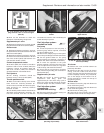
30 Release the locknut and turn the main idle
speed screw in the throttle valve housing until
the engine idles at the specified speed. This
should be all that is necessary to obtain the
correct idle speed, as the throttle valve plate
base setting is set during production.
However, if wear has taken place, or incorrect
adjustment has been carried out previously,
proceed in the following way.
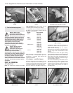
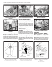
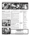
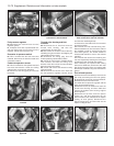
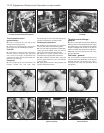
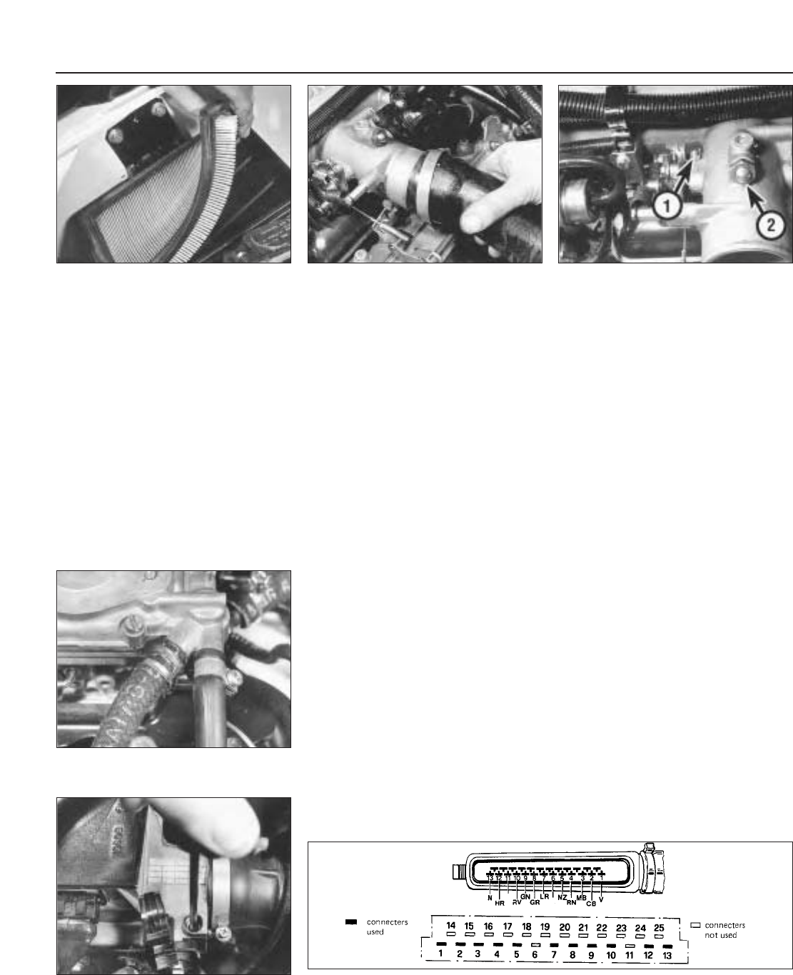
31 Disconnect the intake duct from the
throttle valve housing. Release the locknut on
the base (small) adjusting screw, and turn the
screw until there is a clearance between the
lower edge of the throttle valve plate and the
throat wall of between 0.05 and 0.1 mm
(photos).
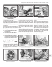
32 With the engine still at operating
temperature, start the engine, and having
released the locknut, turn the main (large) idle
speed screw fully clockwise to close the
bypass passage.
33 Now turn the base (small) screw until the
engine idles at between 700 and 800 rpm.
Tighten the locknut.
34 Finally, turn the main (large) adjusting
screw to give an idle speed of between 800
and 900 rpm.
35 It is unlikely that the mixture will require
alteration, but if it does, connect an exhaust
gas analyser to the car in accordance with the
equipment manufacturer’s instructions.
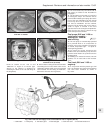
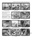
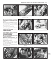
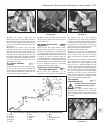
36 With the engine at operating temperature,
prise out the tamperproof cap, and turn the
mixture screw, which is located in the airflow
meter, until the CO level is as given in the
Specifications. Turning the screw clockwise
richens the mixture, turning it anti-clockwise
weakens the mixture. Use a close-fitting Allen
key for the adjustment (photo).
Fuel injection system -
electrical tests ™
37 When carrying out checks to trace a fault
in the system, an ohmmeter should be used
for the following tests.
38 Disconnect the multipin connector from
the ECU, and also the one from the system
control relay, and apply the probes of the
ohmmeter in accordance with the following
sequence to check for continuity in the
cables. The component wiring plug will of
course be disconnected for the test.
ECU connector Component connector
plug terminal plug terminal
1 1 of ignition coil
2 2 of throttle position
switch
3 3 of throttle position
switch
4 50 of ignition switch
5 Earth
5 5 of airflow meter
7 7 of airflow meter
8 8 of airflow meter
9 9 of airflow meter
9 9 of throttle position
switch
9 18 of supplementary air
valve
9 87 main relay socket
10 10 of coolant temperature
sensor
12 Injector terminals
13 Earth
System control Component connector
relay connector plug terminal
plug terminal
1 1 of ignition coil
15 15 of ignition switch
30 Battery positive
31 Earth
50 50 of ignition switch
87 Injector terminals
87 18 of throttle position
switch
87 9 of ECU multipin socket
87b Fuel pump (fused)
13•68 Supplement: Revisions and information on later models
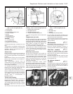
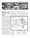
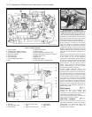
Fig. 13.42 ECU and component connector plug terminals - 1301 cc Turbo ie engine (Sec 9C)
For colour code see main wiring diagrams
9C.31C Checking throttle valve plate
opening with a feeler blade
9C.36 Using an Allen key to adjust the
mixture (CO level)
9C.31B Idle speed base setting screw (1)
and main adjustment screw (2)
9C.31A Disconnecting the throttle valve
housing intake duct
9C.27B Removing the air cleaner element