


necessary renovated as described later in this
Section.
191 Commence refitting as follows.
192 Clean the backs of the bearing shells and
the recesses in the connecting rods and
big-end caps.
193 Lubricate the cylinder bores with engine
oil.
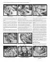
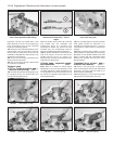
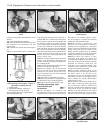
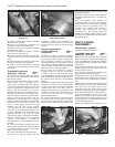
194 Fit a ring compressor to No. 1 piston, then
insert the piston and connecting rod into No. 1
cylinder. With No 1 crankpin at its lowest point,
drive the piston carefully into the cylinder with
the wooden handle of a hammer (photos).
Leave enough space between the connecting
rod and the crankshaft to allow the bearing
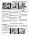
shell to be fitted. The piston must be fitted with
the cut-out in the piston crown on the auxiliary
shaft side of the engine, and the cylinder identi-
fication marking on the connecting rod and
big-end cap on the coolant pump side of the
engine - see Fig. 13.21.
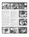
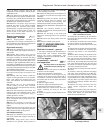
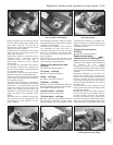
195 Slide the appropriate bearing shell into
position in the connecting rod big-end, then
pull the connecting rod firmly into position on
the crankpin (photo).
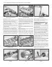
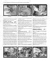
196 Press the appropriate bearing shell into
position in the big-end cap (photo).
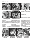
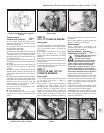
197 Oil the crankpin, then fit the big-end
bearing cap with the cylinder identification
marking on the coolant pump side of the
engine, and tighten the nuts to the specified
torque setting (photos).
198 Check that the crankshaft turns freely.
199 Repeat the procedure in paragraphs 194
to 198 inclusive on the remaining pistons.
200 Refit the cylinder head and the sump.
Pistons/connecting rods -
examination and
renovation #
201 The procedures for inspecting and
renovating the pistons and connecting rod
assemblies are in general the same as that
described for the smaller engines in Sec-
tion 18 of Chapter 1. However, the following
additional points should be noted.
202 When renewing a gudgeon pin, first
check the fit in the piston. It should be
possible to fit the gudgeon pin using hand
pressure, but the pin should be a tight enough
fit that it does not drop out under its own
weight. Oversize gudgeon pins are available
as spares if necessary. Use new circlips when
refitting the pistons to the connecting rods.
203 Before fitting the pistons to their
connecting rods, weigh each piston and
check that their weights are all within 2.5 g of
each other. If not, the heavier pistons must be
lightened by machining metal from the
underside of the small-end bosses. This
operation must be entrusted to a FIAT dealer
or engine reconditioning specialist.
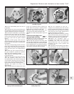
204 The pistons should be fitted to the
connecting rods so that the higher, flat side of
the piston crown is on the side of the
connecting rod with the stamped cylinder
identification number, ie the gudgeon pin is
offset towards the cylinder identification
number see Fig. 13.21.
205 The piston rings should be fitted with the
word “TOP” on each ring facing uppermost,
or if no marks are visible, as noted during
removal. If a stepped top compression ring is
being fitted, fit the ring with the smaller
diameter of the step uppermost. The ring end
gaps should be offset 120º from each other.
Use two or three old feeler gauges to assist
13•48 Supplement: Revisions and information on later models
7B.197B . . . and tighten the nuts to the
specified torque
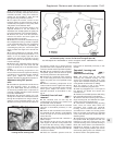
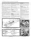
Fig. 13.21 Correct orientation of piston
and connecting rod in engine - 1372 cc ie
and Turbo ie engines (Sec 7B)
1 Auxiliary shaft
2 Cylinder identification markings on
connecting rod and big-end cap
Arrow denotes direction of engine rotation
Note offset gudgeon pin
7B.197A . . . then fit the cap . . .7B.196 . . . and big-end bearing cap . . .
7B.195 Assemble the shell bearing to the
connecting rod . . .
7B.194B Tapping a piston into its bore7B.194A Fitting a ring compressor to a
piston