


Coolant pump -
removal and refitting #
11 The coolant pump is located on the
crankshaft pulley end of the engine and is
driven by the timing belt.
12 The pump cannot be repaired and must
be regarded as disposable.
13 Drain the cooling system.
14 Remove the timing belt cover and then set
No. 1 piston to TDC. To achieve this, turn the
crankshaft pulley bolt until the camshaft
sprocket timing mark is aligned with the one
on the cylinder head.
15 Release the belt tensioner and slip the
timing belt off the camshaft and coolant pump
sprockets.
16 Unbolt and remove the coolant pump and
clean the mounting face of all old gasket
material.
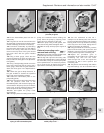
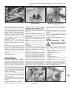
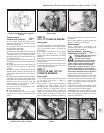
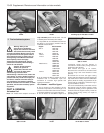
17 Apply a continuous bead of RTV silicone
sealant (instant gasket) to the mounting face
of the coolant pump and bolt it into position
(photos).
18 Check that the camshaft sprocket and the
crankshaft have not been moved and fit the
timing belt to the camshaft and coolant pump
sprockets. The pump sprocket does not
require setting in any particular position
before connecting the timing belt.
19 Tension the belt as described in Sec-
tion 5B of this Chapter.
20 Fit the timing belt cover.
21 After allowing one hour for the gasket
material to cure, refill and bleed the cooling
system.
PART B:
1301 CC TURBO IE ENGINE
Description
1 The cooling system on this model has flow
and return connections to the turbocharger,
and is an essential means of cooling the
turbocharger.
2 The radiator cooling fan is of two-speed
type, being controlled by a two-stage
thermostatic switch screwed into the radiator
side tank.
3 According to the coolant temperature level,
the fan speed is regulated to provide the most
effective cooling.
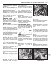
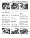
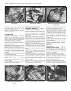
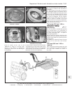
4 The remote cooling system expansion tank
is mounted in the left-hand rear corner of the
engine compartment (photo).
PART C:
1372 CC IE AND 1372 CC
TURBO IE ENGINES
Description
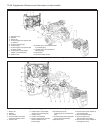
1 The cooling system layout and components
for the 1372 cc engines is shown in
Figs. 13.29 and 13.30.
2 The system on each engine operates in
essentially the same manner as that
described for the other models in Chapter 2,
but the location of components and the
coolant hose routings differ according to
model. The cooling system expansion tank
location differs according to model, being
either located on the side of the radiator or
mounted separately on the side of the inner
wing panel.
3 On Turbo models, the cooling system also
assists in cooling the turbocharger.
Maintenance
4 The maintenance procedures are
essentially the same as those described for
the other models in Chapter 2.
Cooling system - draining,
flushing and refilling ¡
Warning: Wait until the engine is
cold before starting this
procedure. Do not allow
antifreeze to come into contact
with your skin or painted surfaces of the
vehicle. Rinse off spills immediately with
plenty of water. Never leave antifreeze
lying around in an open container or in a
puddle in the driveway or on the garage
floor. Children and pets are attracted by its
sweet smell. Antifreeze is fatal if ingested.
5 Disconnect the battery negative lead.
6 Working inside the vehicle, turn the heater
temperature control knob fully to the right,
which will fully open the heater coolant valve.
7 With the expansion tank cap removed,
place a suitable container beneath the
radiator bottom hose.
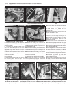
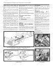
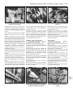
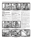
8 Loosen the clip and ease the bottom hose
away from the radiator outlet (photo). Allow
the coolant to drain into the container.
9 Reposition the container under the front of
the cylinder block, and unscrew the cylinder
block drain plug (photo). Allow the coolant to
drain into the container.
Supplement: Revisions and information on later models 13•55
8A.17B Tightening the coolant pump bolts8A.17A Fitting the coolant pump to the
999 cc engine
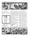
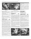
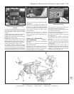
Fig. 13.28 Sectional view of the coolant
pump on the 999 and 1108 cc engines
(Sec 8A)
8C.9 Cylinder block drain plug8C.8 Bottom hose connection to the
radiator
8B.4 Topping up the expansion tank with
antifreeze on the 1301 cc engine
13