


fluid. They are “sealed”. Liquid will get in, but
a thorough clean will be impracticable, and it
will be impossible to get new grease in.
17 Check all the parts, get a new gland, two
new grommets, (1116 cc and 1301 cc) and a
new gasket. Scrape all deposits out of the
housing and off the impeller.
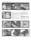
18 To reassemble, start by inserting the new
grommets (1116 cc and 1301 cc) in the
grooves by each bearing. Fit the circlip to the
shaft, then the shouldered ring, bearings and
spacer. Fit the shaft and bearing assembly
into the cover. Fit the stop screw. Press on
the pulley.
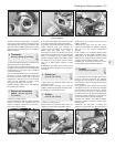
19 Fit the new gland (seal), seating it in its
location in the cover. Press the impeller onto
the shaft. The impeller must be put on part
way, and then the housing held in place to see
how far the impeller must go down the shaft
to give the correct clearance, which is 0.8 to
1.3 mm (0.03 to 0.05 in) as shown in Figs. 2.4
and 2.5.
20 The impeller clearance can be checked
through the coolant passage in the side of the
pump.
21 Refitting is a reversal of the removal
process, but use a new flange gasket and
tension the drivebelt as described in Section 8
(photo).
22 Refill the cooling system.
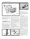
10 Cooling system sensors
1 A coolant temperature sender switch is
located in the cylinder head (above No. 1
spark plug) on 903 cc engines and adjacent to
No. 2 spark plug on 1116 cc and 1301 cc
engines.
2 The switch operates the coolant
temperature gauge and an excessive
temperature warning lamp.
3 On some models, a level sensor is screwed
into the side of the expansion tank. This
sensor consists of a pair of reed switches
within a capsule which are kept closed by the
strong magnetic flux generated by the
hydrostatic force inspired by the action of the
coolant against the float.
4 If the coolant level drops then the magnetic
flux is weakened and the switches open.
5 In the event of a fault developing, before
assuming that the cause is the sensor, check
all connecting wiring.
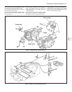
11 Heating and ventilation
system - description
1 The heater is centrally mounted under the
facia and is of fresh air type.
2 Air is drawn in through the grille at the base
of the windscreen. It then passes through the
coolant heated matrix when it can then be
distributed through selective outlets
according to the setting of the control levers.
3 A booster fan is provided for use when the
car is stationary or is travelling too slowly to
provide sufficient air ram effect.
4 Fresh air outlets are provided at each end
and centrally on the facia panel.
12 Heater unit -
removal and refitting
1
1 Drain the cooling system.
2 Disconnect the heater hoses at the engine
compartment rear bulkhead.
3 Working within the car under the facia
panel, disconnect the leads from the
heater blower by pulling the connecting plug
apart.
4 If a radio is fitted, disconnect the
aerial, earth, speaker and power leads from
it.
Cooling and heating systems 2•5
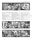
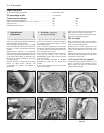
Fig. 2.6 Checking impeller clearance
(Sec 9)
9.21 Fitting coolant pump (1116 cc engine)
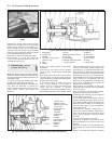
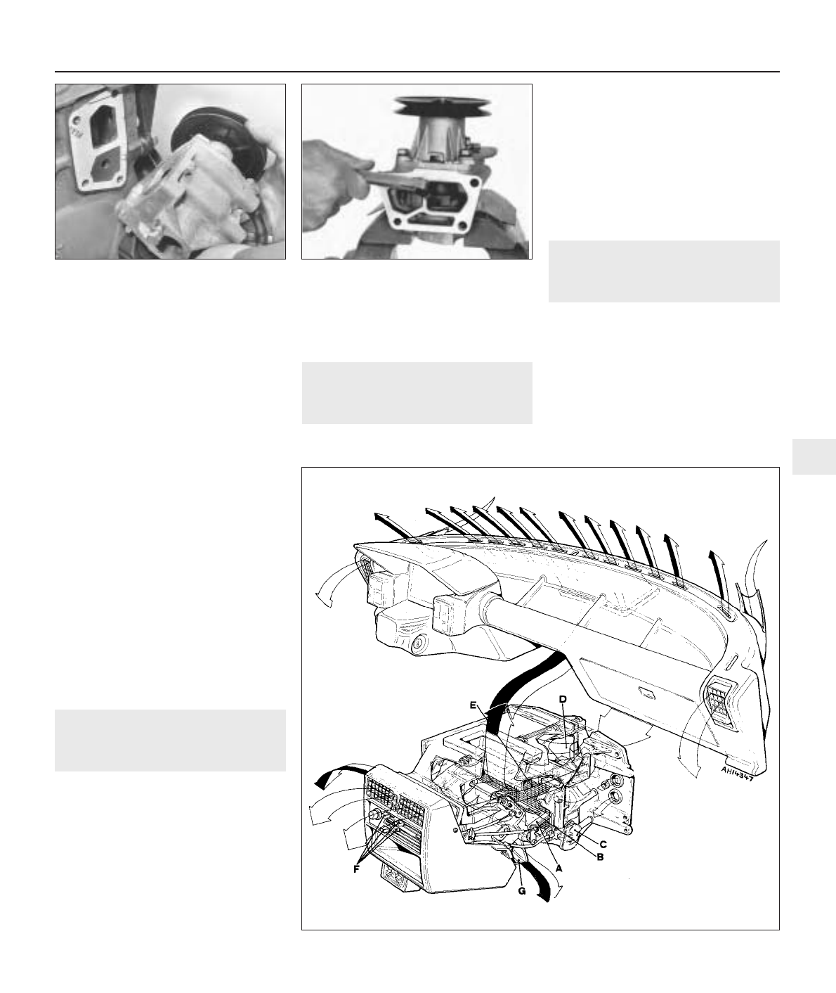
Fig. 2.7 Heater and ventilation system (Sec 11)
A Fresh air inlet flap
B Air distribution flap
C Coolant valve
D Blower
E Matrix
F Control levers
G Footwell air duct
2