


Note: Before diagnosing steering faults, be
sure that trouble is not due to incorrect or
uneven tyre pressures, inappropriate tyre
combinations, or braking system or
suspension defects.
Car pulls to one side
ⅥⅥ Incorrect steering geometry
ⅥⅥ Collision damage
Vibration at steering wheel
ⅥⅥ Roadwheels out of balance or loose
ⅥⅥ Tyre damage
ⅥⅥ Loose driveshaft-to-hub nuts
Car wanders
ⅥⅥ Play in steering gear
ⅥⅥ Wear in steering balljoints
Heavy or stiff steering
ⅥⅥ Lack of lubricant in steering gear or balljoints
ⅥⅥ Incorrect steering geometry
ⅥⅥ Collision damage
Play at steering wheel
ⅥⅥ Wear in steering rack or balljoints
ⅥⅥ Loose steering shaft coupling pinch-bolt or
worn splines
ⅥⅥ Worn steering column/shaft universal joints
Rattles from steering
ⅥⅥ Steering damper defective or in need of
adjustment
ⅥⅥ Loose steering column mounting bolts
ⅥⅥ Loose steering column/shaft coupling
pinch-bolts
ⅥⅥ Loose steering rack housing mounting bolts
ⅥⅥ Worn steering shaft bushes
Excessive or uneven tyre wear
ⅥⅥ Incorrect steering geometry
ⅥⅥ Worn steering components
ⅥⅥ Collision damage
wear. Before considering the steering angles,
check that the tyres are correctly inflated, that
the front wheels are not buckled, the hub
bearings are not worn or incorrectly adjusted
and that the steering linkage is in good order,
without slackness or wear at the joints.
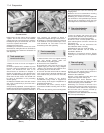
2 Wheel alignment consists of four factors:
Camber, is the angle at which the road
wheels are set from the vertical when viewed
from the front or rear of the vehicle. Positive
camber is the angle (in degrees) that the wheels
are tilted outwards at the top from the vertical.
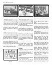
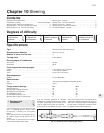
Castor, is the angle between the steering
axis and a vertical line when viewed from each
side of the vehicle. Positive castor is indicated
when the steering axis is inclined towards the
rear of the vehicle at its upper end.
Steering axis inclination, is the angle when
viewed from the front or rear of the vehicle
between vertical and an imaginary line drawn
between the upper and lower suspension
strut mountings.
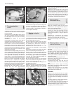
Toe, is the amount by which the distance
between the front inside edges of the
roadwheel rims differs from that between the
rear inside edges.
3 If the distance between the front edges is
less than that at the rear, the wheels are said
to toe-in. If the distance between the front
inside edges is greater than that at the rear,
the wheels toe-out.
4 Camber and castor are set during
production of the car and are not adjustable.
Any deviation from specification will be due to
collision damage or to gross wear in the
components concerned.
5 To check the front wheel alignment, first
make sure that the lengths of both tie-rods are
equal when the steering is in the straight-ahead
position. Measure between the locknut at the
balljoint and the ball cup at the end of the rack
housing by passing a thin rod under the rack of
the gaiter. If adjustment is required, release the
locknut and turn the tie-rod.
6 Obtain a tracking gauge. These are
available in various forms from accessory
stores or one can be fabricated from a length
of steel tubing suitably cranked to clear the
sump and bellhousing and having a setscrew
and locknut at one end.
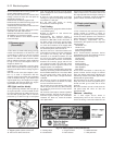
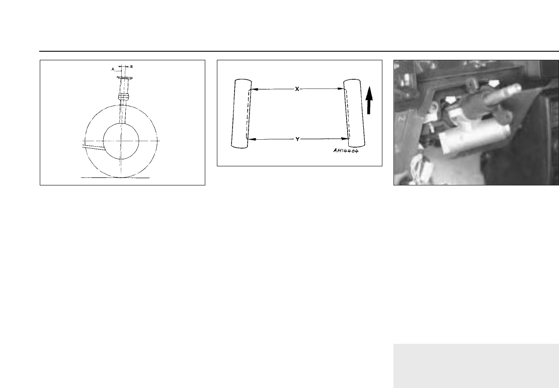
7 With the gauge, measure the distance
between the two wheel inner rims (at hub
height) at the rear of the wheel. Push the
vehicle forward to rotate the wheel through
180º (half a turn) and measure the distance
between the wheel inner rims, again at hub
height, at the front of the wheel. This last
measurement should differ from (be less than)
the first by the appropriate toe-in according to
the Specification (see Specifications Section).
8 Where the toe-in is found to be incorrect,
release the tie-rod balljoint locknuts and turn
the tie-rods equally. Only turn them a quarter
of a turn at a time before re-checking the
alignment. Viewed from the centre line of the
car, turning the tie-rod clockwise will
decrease the toe-in.
9 Make sure that the gaiter outboard clip is
released otherwise the gaiter will twist as the
tie-rod is rotated.
10 Always turn both rods in the same
direction when viewed from the centre line of
the vehicle otherwise the rods will become
unequal in length. This would cause the
steering wheel spoke position to alter and
cause problems on turns with tyre scrubbing.
11 On completion, tighten the tie-rod balljoint
locknuts without altering their setting. Check
that the balljoint is at the centre of its arc of
travel and then retighten the gaiter clip.
9 Steering column lock -
removal and refitting
1
1 Remove the steering wheel and column
shrouds as described in Section 5, also the
steering column combination switch.
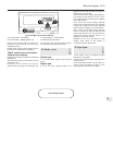
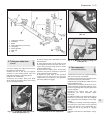
2 Unscrew and remove the steering column
mounting bolts and lower the column to
expose the lock shear bolts.
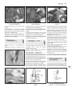
3 Drill out the bolts or extract them using an
extractor.
4 Refer to Chapter 4 for details of separation
of the ignition switch from the lock section.
5 When fitting the new lock, tighten the shear
bolts until their heads break off.
6 Bolt up the column, fit the combination
switch, shrouds and steering wheel and
tighten all nuts and bolts to the specified
torque.
10•4 Steering
Fig. 10.9 Steering column lock shear bolts
(arrowed) (Sec 9)
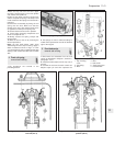
Fig. 10.8 Front wheel alignment diagram
(Sec 8)
X Front dimension Y - X = Toe-in
Y Rear dimension
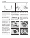
Fig. 10.7 Castor angle (Sec 8)
A Vertical line B Castor angle (positive)
Fault finding - steering