


fitting, as during removal. Note that the
compression rings are brittle, and will snap if
expanded too far.
206 If new pistons are to be fitted, they must
be selected from the grades available, after
measuring the cylinder bores. Normally, the
appropriate oversize pistons are supplied by
the dealer when the block is rebored.
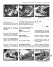
207 Whenever new piston rings are being
installed, the glaze on the original cylinder
bores should be removed using either
abrasive paper or a glaze-removing tool in an
electric drill. If abrasive paper is used, use
strokes at 60º to the bore centre-line, to
create a cross-hatching effect.
Engine/transmission
mountings - renewal ¡
208 The engine/gearbox assembly is
suspended in the engine compartment on
three mountings, two of which are attached to
the gearbox, and one to the engine.
Right-hand mounting
209 Apply the handbrake, then jack up the
front of the vehicle and support it securely on
axle stands.
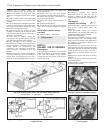
210 Suitable lifting tackle must now be
attached to the engine in order to support it as
the engine mounting is removed. No lifting
brackets are provided, so care must be taken
when deciding on an engine lifting point. In the
workshop, a right-angled bracket was made up
by bending a suitable piece of steel plate. The
bracket was then bolted to the engine using the
rear right-hand camshaft housing securing bolt
with suitable packing washers.
211 Attach the lifting tackle to the bracket on
the engine and just take the weight of the
assembly.
212 Working under the vehicle, unbolt the
engine mounting bracket from the cylinder
block, and unbolt the mounting from the
body, then withdraw the bracket/mounting
assembly.
213 Unscrew the nut and through-bolt,
counter holding the bolt with a second
spanner or socket, and separate the mounting
from the bracket.
214 Fit the new mounting to the bracket, and
tighten the nut to the specified torque, while
counterholding the through-bolt using a
suitable spanner or socket.
215 Refit the mounting bracket to the cylinder
block, and tighten the securing bolts to the
specified torque.
216 Refit the mounting to the body and
tighten the securing bolts to the specified
torque.
217 Disconnect the lifting tackle from the
engine, and remove the engine lifting bracket.
218 Lower the vehicle to the ground.
Left-hand mountings
219 Apply the handbrake, then jack up the
front of the vehicle and support it securely on
axle stands.
220 Suitable lifting tackle must now be
attached to the gearbox lifting bracket in
order to support the weight of the assembly
as the mounting is removed.
221 Attach the lifting tackle to the bracket on
the gearbox, and just take the weight of the
assembly.
222 Working under the vehicle, unbolt the
mounting bracket from the gearbox, and
unbolt the mounting from the body, then
withdraw the bracket/mounting assembly.
223 Proceed as described in paragraphs 213
and 214.
224 Refit the mounting bracket to the
gearbox, and tighten the securing bolts to the
specified torque.
225 Refit the mounting to the body and
tighten the mounting bolts to the specified
torque.
226 Disconnect the lifting tackle from the
engine.
227 Lower the vehicle to the ground.
PART C: ENGINE REMOVAL
AND DISMANTLING
Method of removal - general
1 The engine (complete with transmission) is
disconnected and lowered downwards
through the engine compartment, then
withdrawn from the front underside of the car.
1372 cc engine/
transmission - removal
and separation #
Warning: Refer to the beginning
of Section 9 before starting any
work.
2 Depressurize the fuel system as described
in Section 9 of this Chapter.
3 Disconnect the battery negative lead.
4 Mark the position of the hinges on the
underside of the bonnet, then with the aid of
an assistant, unscrew the hinge bolts and lift
the bonnet clear of the car. Store the bonnet
in a safe area.
5 Drain the engine coolant.
6 Drain the engine and transmission oils.
7 Disconnect and remove the air filter.
8 Disconnect the coolant hoses from the
engine, including the hose to the inlet
manifold.
9 Detach the ignition coil (HT) lead from the
distributor.
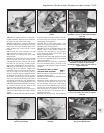
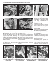
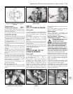
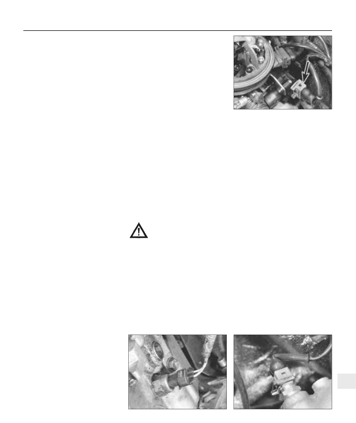
10 Compress the retaining clip and detach
the engine idle speed actuator lead from the
SPi unit (photo).
11 Disconnect the brake servo vacuum pipe
from its connector on the inlet manifold.
12 Disconnect the throttle cable from the SPi
unit.
13 Disconnect the engine speed sensor lead.
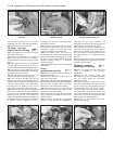
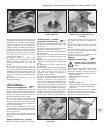
14 Release and detach the reversing light
lead from the switch on the transmission
(photo).
15 Before disconnecting the hydraulic hose
from the clutch slave cylinder, remove the
filler cap from the reservoir and place a piece
of polythene sheet over the filler neck, then
refit the cap; this will help prevent excess fluid
loss. Once disconnected, plug the hose and
its cylinder connection to prevent the ingress
of dirt into the hydraulic system.
16 Disconnect the wiring connector from the
alternator.
17 Position a clean rag under the fuel supply
and return hose connections to the SPi unit,
then slowly unscrew the hose clips to release
the system pressure; catch fuel leakage in the
rag and dispose of it safely. Detach the hoses
and plug them to prevent ingress of dirt and
any further fuel leakage. Position the hoses
out of the way.
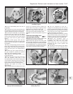
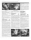
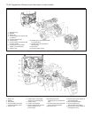
18 Detach the wiring connector from the
engine coolant temperature sender unit
(photo).
19 Release the retaining clip and detach the
wiring connector from the throttle position
switch. Also detach the associated earth
leads from the cylinder head.
Supplement: Revisions and information on later models 13•49
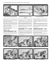
7C.14 Reversing light switch and lead 7C.18 Engine coolant temperature sender
and wiring connector
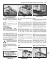
7C.10 Engine idle speed actuator/SPi unit
lead connection (arrowed)
13