


5 In practice, if several shims have to be
changed, they can often be interchanged, so
avoiding the necessity of having to buy more
new shims than is necessary.
6 If more than two or three valve clearances
are found to be incorrect, it will be more
convenient to remove the camshaft carrier for
easier removal of the shims.
7 Where no clearance can be measured, even
with the thinnest available shim in position,
the valve will have to be removed and the end
of its stem ground off squarely. This will
reduce its overall length by the minimum
amount to provide a clearance. This job
should be entrusted to your dealer as it is
important to keep the end of the valve stem
square.
8 On completion, refit the camshaft cover and
gasket.
27 Camshaft and camshaft
carrier - removal and refitting
3
1 Disconnect the battery.
2 Remove the air cleaner (see Chapter 3).
3 Disconnect the fuel filter hose from the fuel
pump and tie it back, out of the way.
4 Identify and then disconnect any electrical
leads which must be moved away to enable
the camshaft cover to be withdrawn.
5 Identify and disconnect any vacuum gases
which must be moved away to enable the
camshaft cover to be withdrawn.
6 Unscrew the securing nuts and remove the
camshaft cover.
7 Turn the crankshaft pulley nut until No. 4
piston is at TDC. This can be established as
described in Section 28.
8 Unbolt and remove the timing belt cover.
9 Check that the timing mark on the camshaft
sprocket is aligned with, and adjacent to the
pointer on the timing belt cover backplate.
10 Restrain the timing belt with the hand and
release but do not remove the camshaft
sprocket bolt. Release the belt tensioner
pulley by slackening the pulley centre nut.
Push the timing belt evenly from the
sprockets, noting which way round the belt is
fitted if it is to be completely removed. The
lettering on the belt is normally legible from
the crankshaft pulley end of the engine when
the belt is as originally fitted.
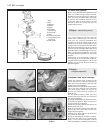
11 Unbolt the camshaft carrier and lift it
sufficiently from the cylinder head to break the
seal of the mating faces. Note: It is important
not to allow the cam followers to pull out; they
must be retained in their original locations.
This can be done if the carrier is raised very
slowly, until the fingers can be inserted to
prise the cam followers onto their respective
valve spring retainers. It is unlikely that the
valve clearance adjusting shims will be
displaced from their recesses in the cam
followers because of the suction of the
lubricating oil, but watch that this does not
happen; the shims must also be retained in
their originally fitted sequence.
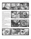
12 Remove the previously loosened
camshaft sprocket bolt and take the sprocket
from the camshaft.
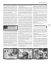
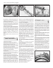
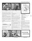
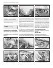
13 Unbolt and remove the camshaft end
cover with its gasket. Withdraw the camshaft
(photos).
14 Refitting is a reversal of the removal
process, but observe the following points.
15 Use new gaskets.
16 Retain the cam followers and shims in
their bores in the camshaft carrier with thick
grease; they must not be allowed to drop out
when the carrier is lowered onto the cylinder
head.
17 If the crankshaft or camshaft have been
moved from their set positions, re-align the
sprocket timing mark with the pointer on the
belt cover and the crankshaft pulley or
flywheel with the TDC mark. This must be
observed otherwise the valves may impinge
upon the piston crowns when the camshaft
lobes compress any of the valve springs
during bolting down of the carrier.
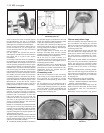
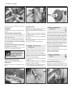
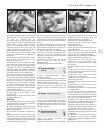
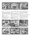
18 Screw in the carrier bolts and tighten
them to the specified torque (photo).
19 Refit and tension the timing belt as
described in Section 28.
20 Refit the camshaft cover and gasket.
21 Refit the hose and air cleaner.
22 Reconnect the battery.
28 Timing belt - renewal
3
1 Set No. 4 piston at TDC. Do this by turning
the crankshaft pulley nut or by jacking up a
front roadwheel, engaging a gear and turning
the wheel until the mark on the flywheel is
opposite to the TDC mark on the flywheel
bellhousing aperture. Remove No. 4 spark
plug, place a finger over the plug hole and feel
the compression being generated as the
crankshaft is rotated and the piston rises up
the cylinder bore.
2 On some models the TDC marks on the
crankshaft pulley and belt cover may be
visible and can be used instead.
3 Remove the alternator drivebelt (Chapter 2,
Section 8). Unbolt and remove the timing belt
cover.
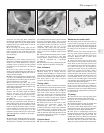
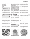
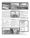
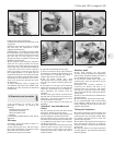
4 Check that the timing mark on the camshaft
sprocket is aligned with the pointer on the belt
cover backing plate (photo).
5 Slacken the nut in the centre of the
tensioner pulley and push in on the support to
release the tension on the belt, then retighten
the nut. Slide the drivebelt off the pulleys.
6 Check that the crankshaft and camshaft
pulleys have not been moved from their
previously aligned positions.
7 To check that the auxiliary shaft sprocket
has not moved, take off the distributor cap
and check that the contact end of the rotor
arm is aligned with No. 4 HT lead contact in
the cap.
1•24 1116 cc and 1301 cc engine
28.4 Camshaft sprocket alignment marks
27.18 Tightening a camshaft carrier bolt27.13B Withdrawing camshaft from carrier27.13A Removing camshaft end cover