


39 Now use the ohmmeter to check the
resistance of the following components.
Supplementary air valve
40 Resistance between the terminals should
be between 40 and 60 ohms at 20ºC (68ºF).
Airflow meter
41 Resistance between terminals 5 and 8 of
the potentiometer should be between 330 and
360 ohms at 20ºC (68ºF).
42 Resistance between terminals 8 and 9 of
the internal circuit should be between 190 and
210 ohms at 20ºC (68ºF) and between 170
and 190 ohms at 60ºC (140ºF).
Coolant temperature sensor
43 At 20ºC (68ºF) the resistance should be
between 2 and 4 k ohms. At 50ºC (122ºF) the
resistance should be between 600 and
900 ohms. At 90ºC (194ºF) the resistance
should be between 100 and 300 ohms.
Fuel injectors
44 The winding resistance should be
between 15 and 17 ohms at 20ºC (68ºF).
Throttle position switch
45 With the throttle butterfly valve closed,
there should be continuity between ter-
minals 18 and 2, and with the valve fully open,
there should be no continuity between
terminals 18 and 3.
46 The throttle position switch should not be
disturbed unless absolutely necessary. If it
has to be removed, then refit it so that the
microswitch is heard to click immediately the
throttle butterfly is opened.
Fuel injection system -
mechanical tests ™
Fuel pump
47 To test the pressure of the fuel pump, a
pressure gauge will be required, connected
into the fuel delivery hose.
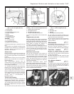
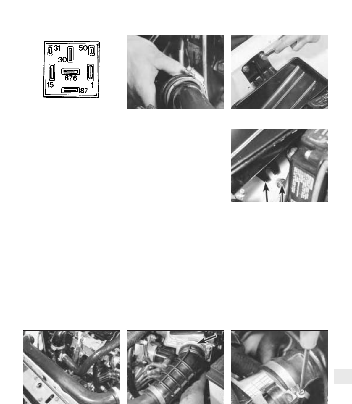
48 Remove the multipin plug from the system
control relay and bridge terminals 87b and 30.
49 Turn the ignition switch on. The pump
should operate and indicate a pressure of
between 2.8 and 3.0 bars (40 and 44 lbf/in
2
).
50 To check the operation of the peak
pressure regulator, pinch the fuel return hose.
If the fuel pressure increases, the regulator
must be faulty, and should be renewed.
51 Check that the fuel pressure increases
when, with the engine idling, the accelerator is
depressed sharply.
Supplementary air valve
52 With the engine at normal operating
temperature and idling, pinch the
supplementary air valve hose using a pair of
pliers. The engine speed should not drop by
more than 50 rpm. If it does, renew the valve.
Fuel injection system
components -
removal and refitting ™
53 Disconnect the battery before carrying out
any of the following operations.
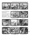
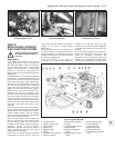
Air cleaner
54 Remove the cover and filter element as
previously described.
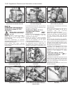
55 Disconnect the duct from the air cleaner
casing, and then unbolt and remove the
casing. Note that the lower bracket bolt need
not be completely removed, only unscrewed,
due to the design of the bracket. The air
cleaner metal duct is routed over the top of
the radiator (photos).
Airflow meter
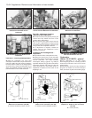
56 Release the securing clip and disconnect
the air intake duct (photo).
57 Release the securing clip and disconnect
the air outlet duct (photo).
58 Disconnect the wiring plug.
59 Unscrew the fixing screws and remove
the airflow meter from its mounting bracket.
Supplement: Revisions and information on later models 13•69
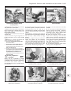
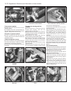
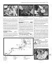
9C.55B Removing the air cleaner casing
upper bracket
9C.55A Disconnecting the duct from the air
cleaner
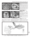
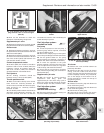
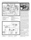
Fig. 13.43 System control relay connector
plug terminals 1301 cc Turbo ie engine
(Sec 9C)
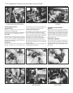
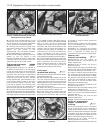
9C.57 Air outlet duct securing clip removal
from airflow meter
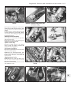
9C.55C Air cleaner casing lower bracket
and bolt (arrowed)
9C.56 Air intake duct at airflow meter
(securing clip arrowed)
9C.55D Air cleaner metal duct over
radiator
13