


PART C: 999 CC AND
1108 CC WITH C514 TYPE
TRANSMISSIONS
Description
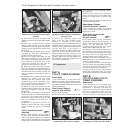
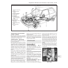
1 A new 5-speed transmission was
introduced to selected models during 1992.
Identified by the way reverse gear is engaged.
The gear knob needs to pressed downwards
whilst pushing the lever to the extreme right.
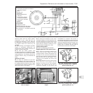
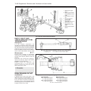
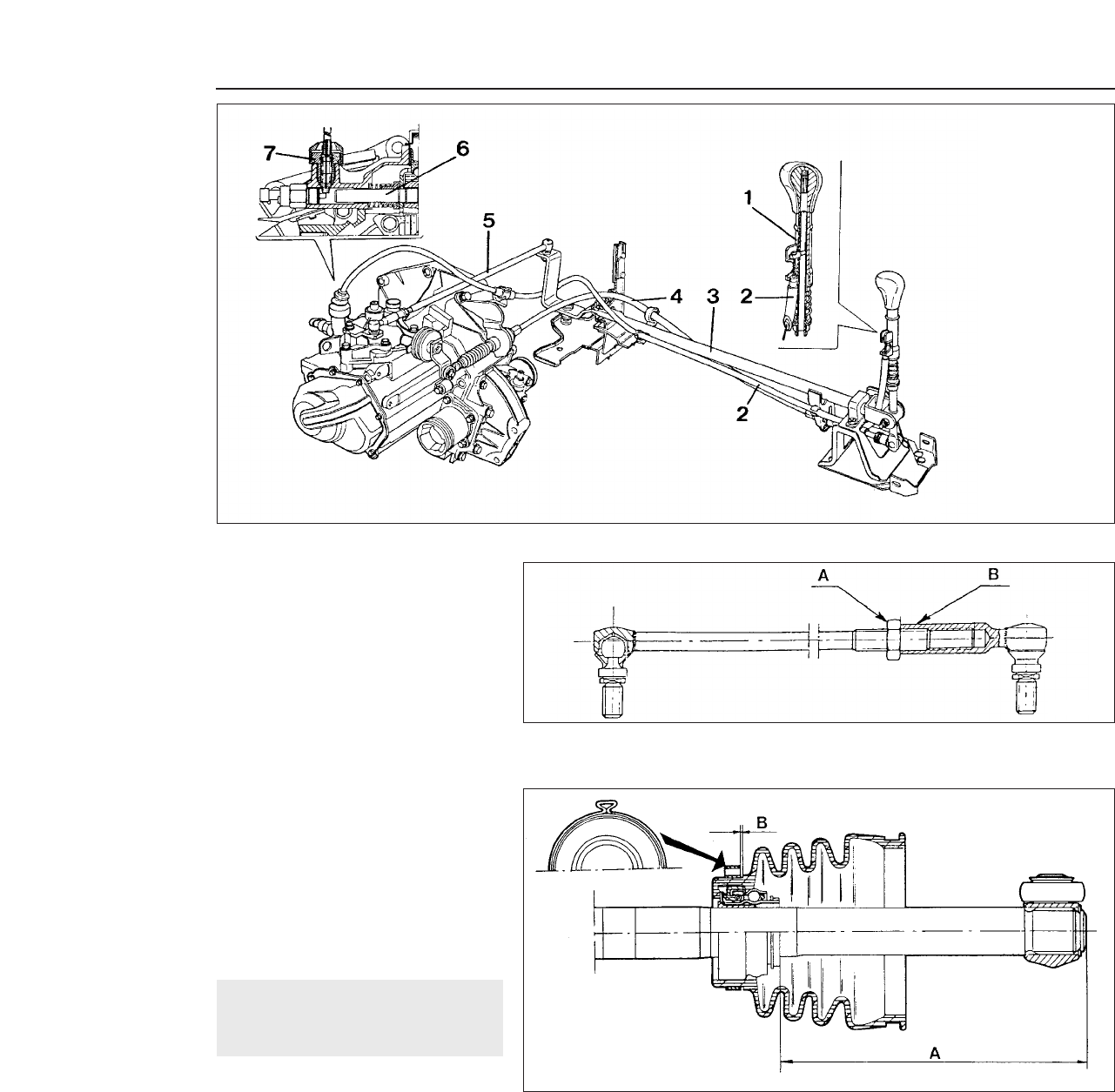
2 The new design includes control cables as
well as rods for gear selection, see Fig. 13.94.
Maintenance ¡
3 At the time of writing, no maintenance
instructions were available, however should
selecting gears become difficult, check the
following.
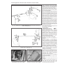
4 The gear lever should rest vertically in
neutral. If it does not, alter the gear selector
adjustable rod, as appropriate.
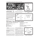
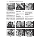
5 Whilst turning the adjustment nut,
counterhold with a 10 mm open ended
spanner, located in the notch built into the
sleeve. Refer to Fig. 13.95.
13 Driveshafts
Inboard joint boots (non-Turbo
models, September 1987 on) -
modification
1 Modified boots have been fitted to the
differential ends of the driveshafts on non-
Turbo models produced after September 1987.
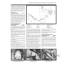
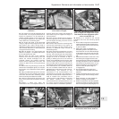
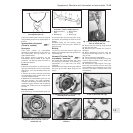
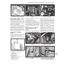
2 The new boots incorporate a seal/bearing
assembly, and it is very important when a
boot is being fitted to the driveshaft that it is
located as shown in Fig. 13.96.
13•98 Supplement: Revisions and information on later models
Fig. 13.96 Driveshaft boot positioning diagram - later non-Turbo models (Sec 13)
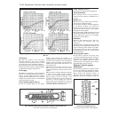
Left-hand shaft
With 4-speed transmission,
A = 143.0 mm (5.63 in)
With 5-speed transmission,
A = 133.0 mm (5.24 in)
Right-hand shaft
With 4-speed transmission,
A = 123.0 mm (4.84 in)
With 5-speed transmission,
A = 108.9 mm (4.25 in)
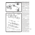
Fig. 13.94 C514 type 5-speed transmission
1 Sliding part of gear
lever
2 Reverse gear inhibitor
device flexible control
cable
3 Gear selector control
rod
4 Gear engagement
control cable
5 Gear selector
adjustable control rod
6 Gear selector and
engagement control
shaft
7 Reverse gear inhibitor
device
B = 0 to 1 mm (0 to 0.04 in)
Fig. 13.95 Gear selector adjustable rod (C514 type transmissions)
A Adjusting nut B Location of notch in outer sleeve