


5 Condenser (capacitor) -
removal, testing and refitting
1
The purpose of the condenser (sometimes
known as the capacitor) is to ensure that when
the contact breaker points open there is no
sparking across them which would weaken
the spark and cause rapid deterioration of the
points.
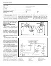
The condenser is fitted in parallel with the
contact breaker points. If it develops a short
circuit it will cause ignition failure as the points
will be prevented from interrupting the low
tension circuit.
1 If the engine becomes very difficult to start
(or begins to misfire whilst running) and the
breaker points show signs of excessive
burning, suspect the condenser has failed
with open circuit. A test can be made by
separating the points by hand with the ignition
switched on. If this is accompanied by a
bright spark at the contact points, it is
indicative that the condenser has failed.
2 Without special test equipment, the only
sure way to diagnose condenser trouble is to
replace a suspected unit with a new one and
note if there is any improvement.
3 To remove the condenser from the
distributor, take out the screw which secures
it to the distributor body and disconnect its
leads from the terminals.
4 When fitting the condenser, it is vital to
ensure that the fixing screw is secure. The
lead must be secure on the terminal with no
chance of short circuiting.
6 Distributor -
removal and refitting
3
1 Remove the spark plug from No. 4 cylinder
and then turn the crankshaft either by
applying a spanner to the pulley nut or by
jacking up a front wheel, engaging top gear
and turning the wheel in the forward direction
of travel.
2 Place a finger over the plug hole and feel
the compression being generated as the
piston rises up the cylinder bore.
3 Alternatively, if the rocker cover is off,
check that the valves on No. 1 cylinder are
closed.
4 Continue turning the crankshaft until the
flywheel and flywheel housing (BTDC) ignition
timing marks are in alignment. Number 4
piston is now in firing position.
5 Remove the distributor cap and place it to
one side complete with high tension leads.
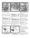
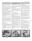
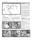
6 Disconnect the distributor vacuum hose
and low tension lead (photo).
7 Mark the distributor pedestal mounting
plinth in relation to the crankcase. Also mark
the contact end of the rotor in relation to the
rim of the distributor body.
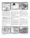
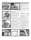
8 Unbolt the clamp plate and withdraw the
distributor.
9 Refit by having No. 4 piston at its firing
position and the distributor rotor and pedestal
marks aligned, then push the distributor into
position, mating it to the splined driveshaft.
10 If a new distributor is being fitted then of
course alignment marks will not be available
to facilitate installation in which case, hold the
unit over its mounting hole and observe the
following.
903 cc engine: Distributor cap high tension
lead sockets pointing towards alternator and
at 90º to centre line of rocker cover. Contact
end of rotor arm pointing towards No. 4
contact in distributor cap (when fitted).
1116 cc and 1301 cc engine: Distributor
vacuum unit pointing downwards at 135º to
rear edge of timing belt cover. Contact end of
rotor arm pointing towards No. 4 contact in
distributor cap (when fitted).
11 Tighten the distributor clamp bolt,
reconnect the vacuum hose and the low
tension leads. Refit the distributor cap. Screw
in the spark plug.
12 Check the ignition timing as described in
Section 4.
7 Distributor (mechanical
breaker type) - overhaul
3
Ducellier
1 The cap must have no flaws or cracks and
the HT terminal contacts should not be
severely corroded. The centre spring-loaded
carbon contact is renewable. If in any doubt
about the cap, buy a new one.
2 The rotor deteriorates minimally, but with
age the metal conductor tip may corrode. It
should not be cracked or chipped and the
metal conductor must not be loose. If in
doubt, renew it. Always fit a new rotor if fitting
a new cap.
3 With the distributor removed as described
in the preceding Section, take off the rotor
and contact breaker.
4 To remove the contact breaker movable
arm, extract the clip and take off the washer
from the top of the pivot post.
5 Extract the screw and remove the fixed
contact arm.
6 Carefully record the setting of the advance
toothed segment and then remove the spring
clip and vacuum capsule fixing screws and
withdraw the capsule with link rod.
7 Pick out the lubrication pad from the recess
in the top of the distributor shaft. Unscrew the
screw now exposed.
8 Mark the relationship of the cam to the
counterweight pins and then remove the cam
assembly.
9 There is no way to test the bob weight
springs other than by checking the
performance of the distributor on special test
equipment, so if in doubt, fit new springs
anyway. If the springs are loose where they
loop over the posts, it is more than possible
that the post grooves are worn. In this case,
the various parts which include the shaft will
need renewal. Wear to this extent would mean
that a new distributor is probably the best
solution in the long run. Be sure to make note
of the engine number and any serial number
on the distributor when ordering.
10 If the mainshaft is slack in its bushes or
the cam on the spindle, allowing sideways
play, it means that the contact points gap
setting can only be a compromise; the cam
position relative to the cam follower on the
moving point arm is not constant. It is not
practical to re-bush the distributor body
unless you have a friend who can bore and
bush it for you. The shaft can be removed by
driving out the roll pin from the retaining collar
at the bottom. (The collar also acts as an oil
slinger to prevent excess engine oil creeping
up the shaft.)
Marelli
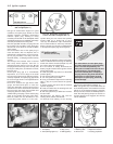
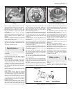
11 With the distributor removed from the
engine, take off the spark shield and rotor.
12 Remove the contact breaker and carrier
as described in Section 2.
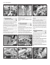
13 Refer to paragraphs 9 and 10 for details of
counterweight springs and shaft bushes
(photo).
Ignition system 4•5
6.6 Distributor LT connection4.5 Distributor clamp plate nut
4