


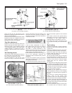
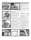
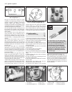

Note the washers above and below the
contact assembly (photos).
23 Fit the new contact assembly by reversing
the removal operations.
24 Although the points gap is normally set in
production, check it using feeler blades when
the plastic heel of the movable arm is on a
high point of the shaft cam. Adjust if
necessary by inserting an Allen key (3.0 mm)
into the socket-headed adjuster screw.
25 Carry out the operations described in
paragraphs 14 to 17 in this Section.
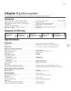
3 Dwell angle - checking
3
The dwell angle is the number of degrees
through which the distributor cam turns
between the instants of closure and opening
of the contact breaker points.
1 Connect a dwell meter in accordance with
the maker’s instruction. The type of meter that
operates with the engine running is to be
preferred; any variation in contact breaker
gap, caused by wear in the distributor shaft or
bushes, or the height of the distributor cam
peaks, is evened out when using this.
2 The correct dwell angle is given in the
Specifications at the beginning of this
Chapter. If the angle is too large, increase the
contact points gap. If the angle is too small,
reduce the points gap. Only very slight
adjustments should be made to the gap
before re-checking.
3 On Ducellier distributors, adjustment of the
dwell angle can only be carried out by
switching off the ignition, removing the
distributor cap, rotor and spark shield and
adjusting the points gap.
4 Re-check once the engine is running.
Adjustment may have to be carried out
several times to obtain the correct dwell
angle.
5 On Marelli distributors, adjustment of the
points gap (dwell angle) is carried out with the
engine running by inserting a 3.0 mm Allen
key in the hole provided in the distributor
body.
6 Always check and adjust the dwell angle
before timing the ignition as described in
Section 4.
4 Ignition timing
3
1 Timing the ignition on engines with
mechanical breaker distributors is carried out
in the following way.
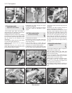
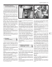
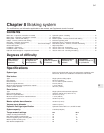
2 Disconnect the vacuum hose from the
distributor diaphragm capsule (photo).
3 Have the engine at normal operating
temperature and idling with a stroboscope
connected in accordance with the
manufacturer’s instructions.
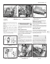
4 Point the stroboscope at the timing marks
on the flywheel and the index on the aperture
on the flywheel housing. The mark on the
flywheel should be opposite to the BTDC
mark on the index specified for your particular
engine. Alternatively, use the notch on the
crankshaft pulley and the marks on the timing
belt cover (photo), but this will necessitate
removal of the wheel arch shield.
5 If the marks are not in alignment, release
the distributor clamp plate and turn the
distributor gently until they are (photo).
6 Tighten the clamp plate nut, switch off the
ignition, reconnect the vacuum hose and
remove the stroboscope.
7 If there is any difficulty in seeing the timing
marks clearly, highlight them by painting with
quick-drying white paint.
4•4 Ignition system
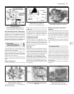
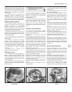
4.4 Ignition timing marks on belt coverFig. 4.5 Flywheel housing timing marks
(Sec 4)
4.2 Distributor vacuum hose
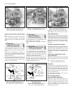
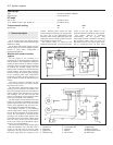
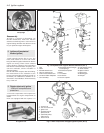
Fig. 4.4 Adjusting Marelli type contact
breaker points gap (Sec 2)
Fig. 4.3 Marelli contact breaker (Sec 2)
2.22B Washers above contact breaker2.22A Marelli contact breaker E-clip