


control unit is functioning, if the tachometer
does not register, renew the ignition control
unit.
16 If a replacement carburettor is to be fitted,
only fit the Solex assembly including the
control module, even if a Weber was originally
fitted.
12 Carburettor
(Weber 32 ICEV 51/250) -
servicing and adjustment
4
1 This carburettor, fitted to 1116 cc engines,
is very similar to the unit described in Sec-
tion 9.
2 The fast idle adjustment procedure is
identical, but note that dimension (A) (Fig.
3.12) should be between 0.85 and 0.90 mm
(0.033 and 0.035 in).
3 The choke valve plate gap (Y) (Fig. 3.13)
should be between 5.5 and 6.5 mm (0.22 and
0.26 in) and if adjustment is required, bend
the stop on the control lever.
13 Carburettor
(Solex C32 DISA 12) -
servicing and adjustment
4
1 This carburettor is an alternative to the
Weber fitted to 1116 cc engines.
2 The adjustments described in Section 9
apply.
14 Carburettor
(Weber 30/32 DMTR 90/250)
- servicing and adjustment
4
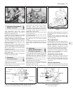
1 The carburettor top cover with float may be
removed without the need to withdraw the
carburettor from the manifold. The other
adjustments described in this Section will
require removal of the carburettor.
2 Extract the top cover fixing screws and lift
away the top cover with float. Access to the
fuel inlet needle valve is as described in
Section 9 paragraphs 4 and 5.
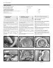
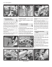
Float adjustment
3 Hold the cover vertically so that the floats
hang down under their own weight. Measure
the distance between the float and the surface
of the gasket on the top cover. This should be
between 6.75 and 7.25 mm (0.27 and 0.29 in).
4 Bend the float arm if necessary to adjust
the setting.
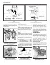
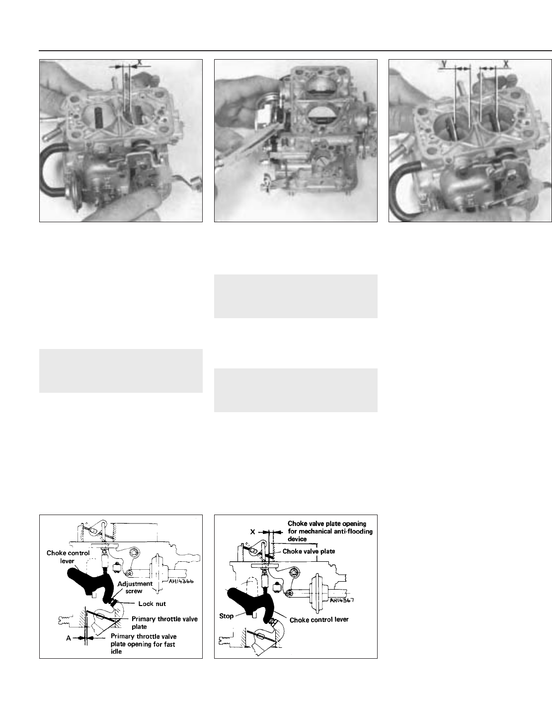
Primary valve plate opening
5 With the throttle valve plate control lever in
contact with the stop, the primary valve plate
should be open (dimension X Fig. 3.22)
between 6.45 and 6.95 mm (0.25 and 0.27 in).
If adjustment is required, carefully bend the
lever stop.
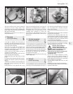
Primary and secondary valve
plate openings
6 With the throttle control lever fully actuated
the valve plate gaps (X and Y Fig. 3.24) should
be:
X = 13.5 to 14.5 mm (0.53 to 0.57 in)
Y = 14.5 to 15.5 mm (0.57 to 0.61 in)
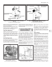
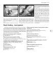
Fast idle
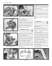
7 Close the choke valve plate fully and check
the gap (A) (Fig. 3.25) between the edge of the
throttle valve plate and the carburettor throat.
The gap should be between 0.90 and
0.95 mm (0.035 and 0.037 in), a twist drill is
useful for measuring this.
8 If adjustment is required, carry this out
using the screw and locknut.
Anti-flooding device
(mechanically-operated)
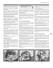
9 With the choke control pulled fully out, it
should be possible to open the choke valve
plate to give a gap (X) of between 7.0 and
7.5 mm (0.28 and 0.30 in). If adjustment is
required, carefully bend the stop on the
control lever (Fig. 3.26).
3•10 Fuel system
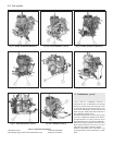
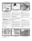
Fig. 3.26 Anti-flooding device (mechanical)
adjustment diagram
(Weber 30/32 DMTR 90/250) (Sec 14)
X = 7.0 to 7.5 mm (0.28 to 0.30 in)
Fig. 3.25 Fast idle adjustment diagram
(Weber 30/32 DMTR 90/250) (Sec 14)
A = 0.90 to 0.95 mm (0.035 to 0.037 in)
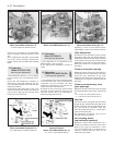
Fig. 3.24 Throttle valve plate openings
(Weber 30/32 DMTR 90/250) (Sec 14)
X (primary) = 13.5 to 14.5 mm (0.53 to 0.57 in)
Y (secondary) = 14.5 to 15.5 mm (0.57 to 0.61 in)
Fig. 3.23 Bending throttle lever stop
(Weber 30/32 DMTR 90/250) (Sec 14)
Fig. 3.22 Primary valve plate opening
(Weber 30/32 DMTR 90/250) (Sec 14)
X = 6.45 to 6.95 mm (0.25 to 0.27 in)