


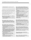

depressurize the fuel system, before
disconnecting the fuel pipes and removing the
throttle body, as described in Section 9D.
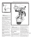
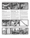
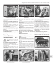
34 Disconnect the coolant and vacuum
hoses from the cylinder head and inlet
manifold (photo).
35 Disconnect the electrical lead from the
coolant temperature switch, the LT leads from
the distributor and the idle cut-off solenoid
lead.
36 Remove the distributor cap, disconnect
the plug leads and place the cap and leads to
one side of the engine compartment.
37 Unbolt and remove the timing belt cover.
38 Set No. 4 piston to TDC and then release
the timing belt tensioner and slip the belt from
the camshaft and coolant pump sprockets.
39 Unbolt and remove the inlet manifold,
complete with carburettor, or throttle body as
applicable.
40 Unbolt the exhaust manifold from the
cylinder head and tie it to one side of the
engine compartment; the downpipe bracket
will have to be disconnected.
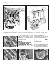
41 Unscrew the cylinder head bolts, a half
turn at a time in the reverse order to that
shown in Fig. 1.30 of Chapter 1. When the
bolts are free, remove them with their
washers.
42 Lift the cylinder head from the block. If it is
stuck tight, insert pieces of wood into the
exhaust or inlet ports and use them as levers
to “rock” the head off the block. On no
account drive levers into the gasket joint or
attempt to tap the head sideways as it is
located on positioning dowels.
43 Remove and discard the cylinder head
gasket and both manifold gaskets.
44 The cylinder head can be dismantled after
removing the camshaft and cam followers as
described in the preceding sub-Section.
45 Further dismantling and decarbonising are
described in Chapter 1, Section 39. Note that
single valve springs are used.
46 If the valves have been ground in, the
valve clearances will require adjusting, as
described previously. This should be done
before the cylinder head is refitted to the
engine.
47 Before refitting the assembled cylinder
head, make sure that the head and block
mating surfaces are perfectly clean, and that
the block bolt holes have been cleared of any
oil.
48 The camshaft sprocket timing mark must
be aligned with the one on the cylinder head.
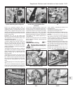
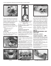
49 The new gasket should not be removed
from its nylon cover until required for use. Fit
the gasket dry to perfectly clean surfaces.
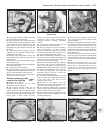
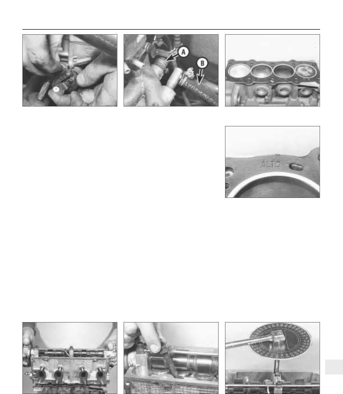
50 Place the gasket on the cylinder block so
that the word ALTO can be read from above
(photos).
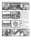
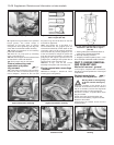
51 Lower the cylinder head onto the block so
that it locates on the positioning dowels
(photo).
52 The cylinder head bolts must have clean
threads, dipped in engine oil and allowed to
drain for thirty minutes. Screw the bolts in
finger-tight and then tighten them in the
sequence shown in Fig. 1.30 of Chapter 1,
and in the stages specified (see Specification)
(photos).
53 Refit the inlet manifold and carburettor
using a new gasket.
54 Reconnect the exhaust manifold using a
new gasket. Tighten all nuts to the specified
torque. Reconnect the exhaust downpipe
bracket.
55 Reconnect the timing belt and tension it
as described earlier.
56 Refit the timing belt cover and the
distributor cap and camshaft cover.
57 Reconnect all hoses, electrical leads and
controls.
58 Fit the air cleaner.
59 Fill and bleed the cooling system.
Supplement: Revisions and information on later models 13•23
5B.50A Cylinder head gasket5B.34 Inlet manifold coolant hose (A) and
brake servo vacuum hose (B)
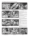
5B.32 Disconnecting the throttle cable
5B.52B Typical disc for angular tightening
of cylinder head bolts
5B.50B Cylinder head gasket top surface
marking
5B.52A Inserting a cylinder head bolt5B.51 Fitting the cylinder head
13