


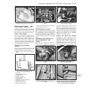
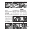
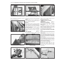
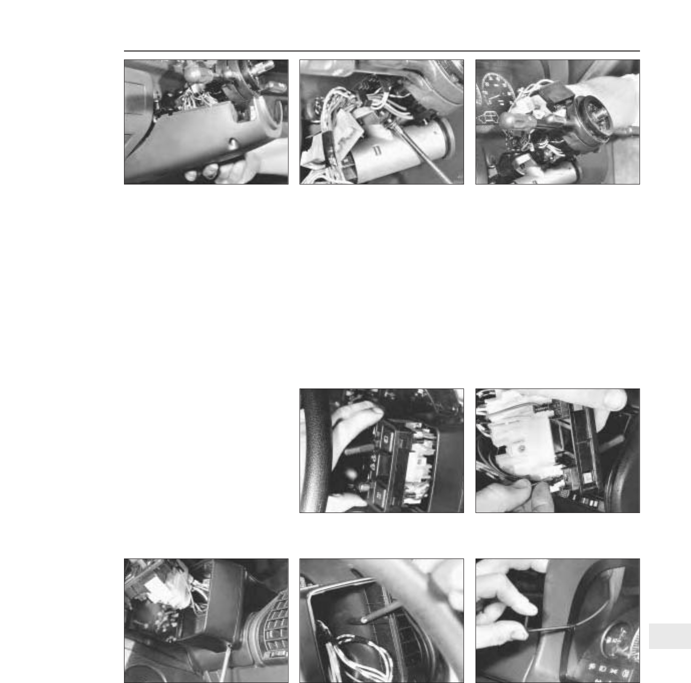
47 Loosen off the switch-to-column clamp
screw, disconnect the wiring connectors to
the switch and withdraw the switch from the
column (photos).
48 Refit in the reverse order of removal, but
ensure that the lug of the switch aligns with
the slot in the column as it is fitted into
position. Check for satisfactory operation of
the switches on completion.
Instrument panel
(Turbo ie models) -
removal and refitting ¡
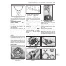
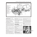
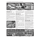
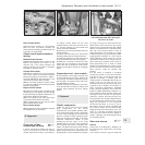
49 The instrument panel on these models
incorporates an engine oil pressure gauge
and a turbo boost gauge. The latter is
connected directly to the inlet manifold.
50 Apart from disconnecting the boost gauge
rubber hose, the instrument panel removal
and refitting procedure is as described in
Chapter 9 for the 1301 cc model or from
paragraph 57 in this Section for the 1372 cc
model.
51 A digital electronic instrument panel is
available as an option on Turbo ie models.
The removal and refitting procedures differ
from analogue instrument panels in respect of
the electrical connections - a speedometer
drive cable is not used.
Facia-mounted switches
(1301 cc Turbo ie model) -
removal and refitting ¡
52 Disconnect the battery.
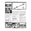
53 Insert a thin-bladed screwdriver into the
joint between the switch block and the switch
block housing, to depress the plastic retaining
tabs. Do this carefully, otherwise the switch
block or casing will be damaged.
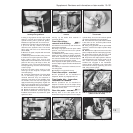
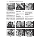
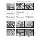
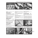
54 Withdraw the switch block. Individual
switches can now be pushed out of the block.
Fibre optics are used to illuminate some
switches, these simply pull out of their
sockets (photos). The illumination bulb is
located on a crossmember found behind the
instrument pack. Removal of instruments/top
cover allows access.
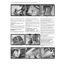
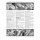
55 The switch housing can be removed after
extracting the fixing screws (photos).
56 Refitting is a reversal of removal.
Instrument panel
(later models) -
removal and refitting ¡
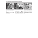
57 Disconnect the battery negative lead.
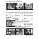
58 Unscrew and remove the two instrument
panel-to-facia retaining screws (photo).
59 Remove the lower facia trim panel, which
is secured by two screws and a nut. Reach up
to the rear of the instrument panel to
disconnect the speedometer cable, then push
the panel from its recess in the facia.
Disconnect the multi-connectors from the rear
face of the panel and withdraw it (photo).
60 Refit in the reverse order of removal.
Ensure that the speedometer cable is fully
engaged as the unit is refitted into position.
Supplement: Revisions and information on later models 13•107
15.47B . . . and remove the column switch15.47A Undo the retaining screw . . .15.45C . . . and the lower column
shroud . . .
15.58 Remove the retaining screws . . .15.55B Facia switch housing inner screw
removal on the 1031 cc Turbo ie model
15.54B Disconnecting a fibre optic cable
from its holder on the 1301 cc Turbo ie
model
15.54A Switch block withdrawal on the
1301 cc Turbo ie model
15.55A Facia switch housing lower screw
removal on the 1301 cc Turbo ie model
13