


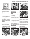
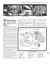
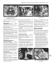
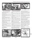
air temperature sensor. Undo the retaining
screw and remove the sensor from the
injector unit (photo).
50 Refit in the reverse order of removal.
Fuel injector -
removal and refitting ¡
51 Depressurise the fuel system as
described previously, then disconnect the
battery negative lead.
52 Remove the air cleaner unit.
53 Release the injector feed wiring mutliplug
and detach it from the injector.
54 Bend over the locking tabs retaining the
injector screws, then undo and remove the
screws. Withdraw the injector retaining collar,
then carefully withdraw the injector (noting its
orientation) followed by its seal.
55 Refit in the reverse order of removal.
Always use new seals in the unit and the
retaining collar and lightly lubricate them with
clean engine oil prior to assembly. Take care
not to damage the seals when fitting and also
when the injector is fitted; check that it
engages correctly.
Fuel injection electronic
control unit (ECU) -
removal and refitting ¡
56 The control unit is located under the facia
on the driver’s side of the vehicle. Commence
by disconnecting the battery negative lead.
57 To gain access to the control unit, detach
and remove the trim panel from the underside
of the facia on the driver’s side of the car.
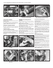
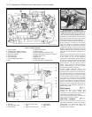
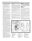
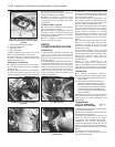
58 Disconnect the wiring multiplug from the
control unit, then undo the retaining screw
and remove the unit from the car (photos).
59 Refit in the reverse order of removal.
Inlet manifold -
removal and refitting ¡
60 Remove the fuel injector unit as described
previously.
61 Drain the cooling system as described in
Section 8 of this Chapter.
62 Detach the coolant hose and coolant
temperature sensor from the inlet manifold.
63 Unbolt and remove the accelerator
cable/throttle linkage support bracket from
the top of the inlet manifold. The cable can be
left attached to the bracket.
64 Detach the brake servo vacuum hose
from the connector on the manifold.
65 Unscrew and remove the inlet manifold
securing bolts and nuts and remove the
manifold from the cylinder head. As they are
removed, note the location of the fastenings
and their spacers.
66 Remove the gasket and clean the mating
faces of the manifold and the cylinder head.
The gasket must be renewed when refitting
the manifold.
67 Refitting is a reversal of the removal
procedure. Ensure that the spacers are
correctly located (where applicable) and
tighten the retaining bolts and nuts to the
specified torque settings.
Exhaust manifold -
removal and refitting ¡
68 Remove the inlet manifold as described
previously (1372 cc models only).
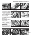
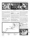
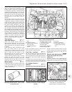
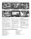
69 Disconnect the Lambda sensor lead
(photo).
70 Raise and support the car at the front end
on axle stands to allow sufficient clearance to
work underneath the car and disconnect the
exhaust downpipe from the manifold.
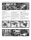
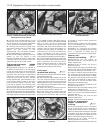
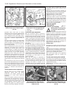
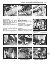
71 Straighten the tab washers, then unscrew
and remove the exhaust downpipe-
to-manifold retaining nuts (photo). Detach the
downpipe from the manifold. Support the
downpipe so that the Lambda sensor will not
get knocked and/or damaged.
72 Undo the manifold-to-cylinder head
securing bolts/nuts and withdraw and remove
the manifold and heat shield.
73 Remove the gasket and clean the mating
faces of the manifold, cylinder head and
downpipe flange. The gasket must be
renewed when refitting the manifold.
74 Refitting is a reversal of the removal
procedure. Tighten the retaining bolts/nuts to
the specified torque setting.
Catalytic converter -
general information
75 The catalytic converter is a reliable and
simple device which needs no maintenance in
itself, but there are some facts of which an
owner should be aware if the converter is to
function properly for its full service life.
a) DO NOT use leaded petrol in a car
equipped with a catalytic converter - the
lead will coat the precious metals,
reducing their converting efficiency and
will eventually destroy the converter.
b) Always keep the ignition and fuel systems
well-maintained in accordance with the
maintenance schedule - particularly, en-
sure that the air cleaner filter element the
fuel filter and the spark plugs are renewed
at the correct interval - if the intake air/fuel
mixture is allowed to become too rich due
to neglect, the unburned surplus will enter
and burn in the catalytic converter,
overheating the element and eventually
destroying the converter.
Supplement: Revisions and information on later models 13•77
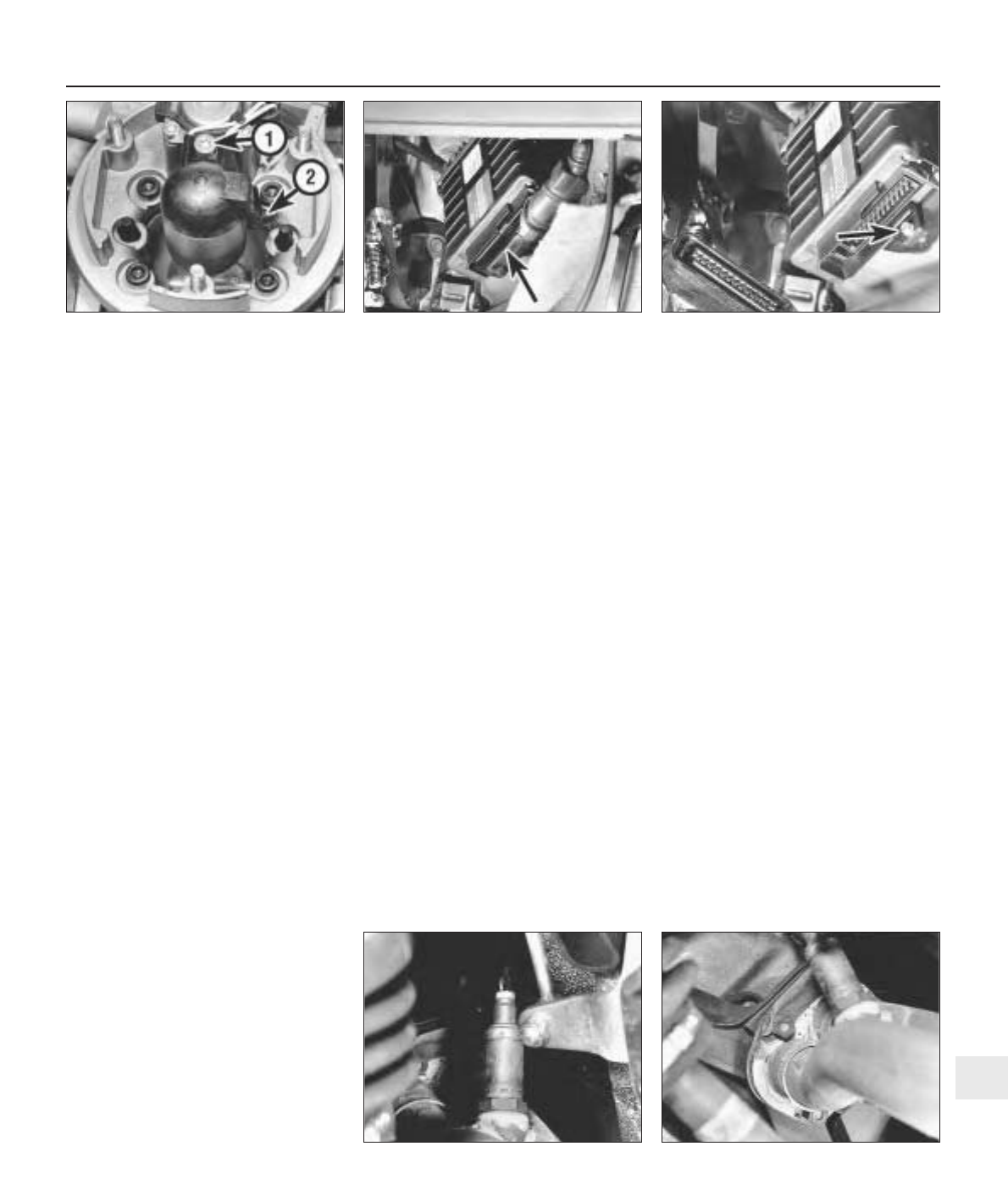
9D.58B . . . for access to the ECU retaining
screw (arrowed)
9D.58A Detach the multiplug (arrowed) . . .9D.49 Fuel injector unit sensor retaining
screw (1). Also shown is the intake air
temperature sensor (2)
9D.71 Exhaust downpipe to manifold
flange connection showing retaining nuts
and locktabs
9D.69 Lambda sensor in exhaust
downpipe
13