


removal are in place under the
engine-to-gearbox bolts. Do not allow the
weight of the gearbox to hang on the input
shaft as it is engaged with the clutch friction
disc.
29 Refit the starter motor, ensuring that the
wiring harness bracket is in position on the
top bolt.
30 Locate the engine/transmission unit at the
front of the car and move it into position under
the engine compartment. Attach the lifting
sling and hoist as during removal.
31 Enlist the aid of an assistant to help
steady the combined units as they are raised
into position and to locate the mountings in
the engine compartment.
32 Once they are located, tighten the
mountings to the specified torque settings,
then disconnect the lifting hoist and sling.
33 The remainder of the refitting and
reconnection procedures are a reversal of the
removal procedure described in Part C. For
further details on reconnecting the
suspension and driveshaft components,
refer to Chapter 7 and Section 13 of this
Chapter.
34 Ensure that the exhaust downpipe-to-
manifold connection is clean and renew the
gasket when reconnecting this joint. Use a
smear of exhaust assembly paste on the joint
faces. Use new lockwashers and tighten the
flange nuts securely.
35 Ensure that all fuel and coolant
connections are cleanly and securely made.
36 Ensure that all wiring connections are
correct and securely made.
37 Top up the engine and transmission oil
levels.
38 Refill the cooling system.
39 Check that all connections are securely
made, then reconnect the battery negative
lead.
Initial start-up after major
overhaul
40 Refer to Chapter 1, Section 45.
8 Cooling system
PART A:
999 AND 1108 CC ENGINES
Description
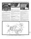
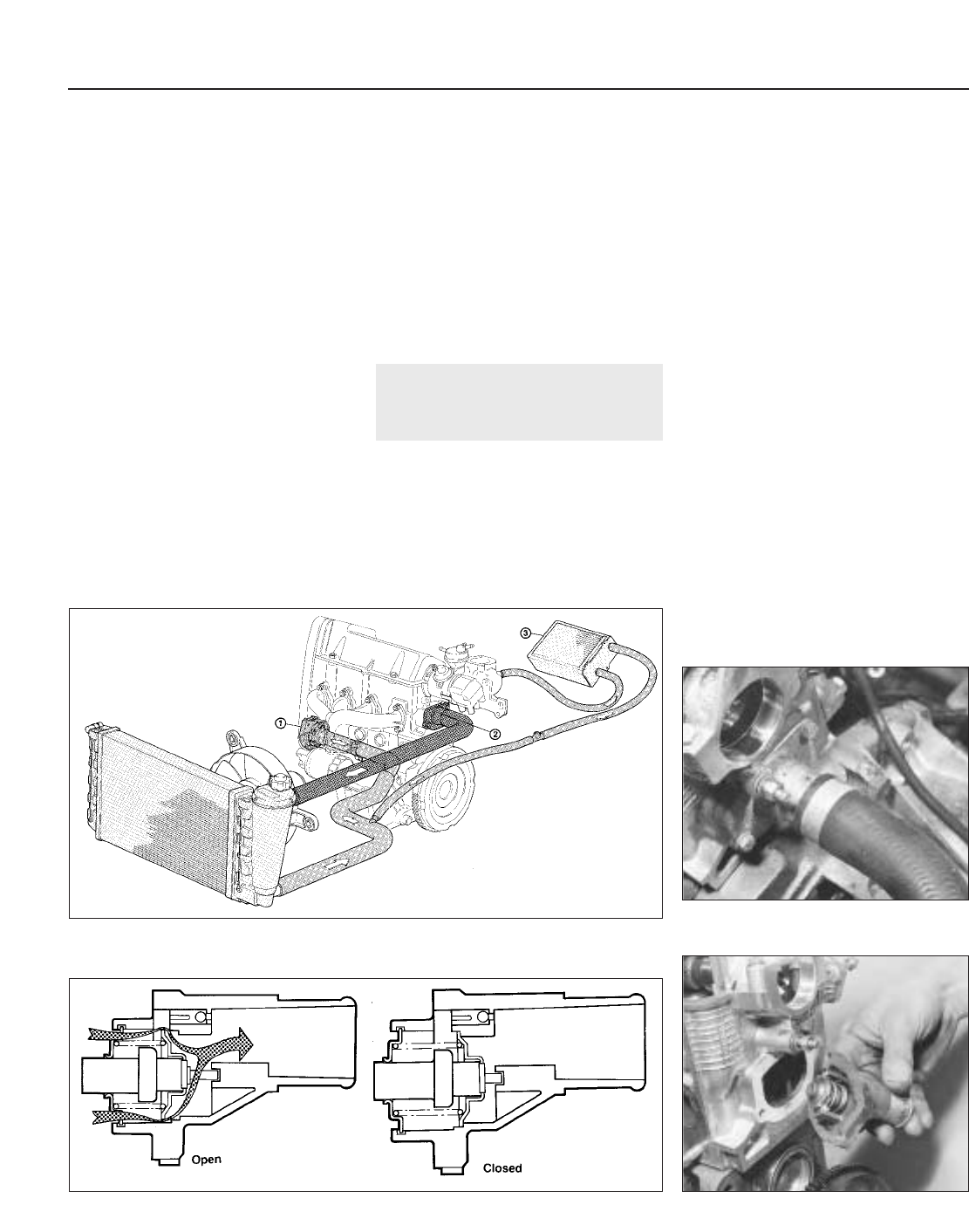
1 The operation and function of the cooling
system is essentially as described in Chapter
2 but note the location of the various
components and the routing of the coolant
hoses in Fig. 13.26.
Maintenance
2 Topping-up, draining and refilling
procedures are as for 1116 and 1301 cc
engines in Chapter 2, but note that the
coolant capacity is different (see Specifica-
tions).
Thermostat -
removal and refitting ¡
3 The thermostat is located on the left-hand
end of the cylinder head, below the
distributor.
4 The thermostat cannot be renewed
independently of its housing and if faulty the
complete assembly must be renewed.
5 Drain the cooling system.
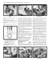
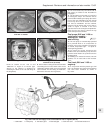
6 Although the thermostat housing can be
removed directly from the cylinder head,
better access is provided if the distributor is
first withdrawn as described in Section 10 of
this Chapter (photo).
7 Disconnect the coolant hose from the
thermostat housing and unscrew the housing
flange bolts. Remove the assembly. Note that
it may be necessary to tap it free with a
plastic-faced or wooden mallet if stuck in
place.
8 Remove the gasket and clean the mating
surfaces.
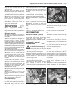
9 Use a new gasket and bolt the assembly
into position (photo).
10 Reconnect the coolant hose, then fill and
bleed the cooling system.
13•54 Supplement: Revisions and information on later models
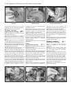
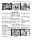
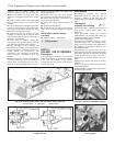
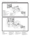
Fig. 13.26 Cooling system circuit - 999 and 1108 cc engines (Sec 8A)
1 Coolant pump 2 Thermostat 3 Heater matrix
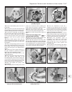
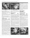
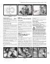
Fig. 13.27 Cooling system thermostat in open and closed positions - 999 and 1108 cc
engines (Sec 8A)
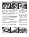
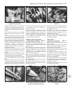
8A.9 Fitting the thermostat housing. Note
the new gasket
8A.6 The thermostat housing (shown with
distributor removal) on the 999 cc engine