


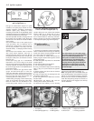
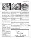

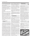
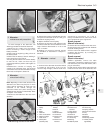
The hose ends can then be unclipped from
the brackets. The mounting brackets,
particularly on the body frame, are not very
heavy gauge and care must be taken not to
wrench them off (photo).
4 With the flexible hose removed, examine
the internal bore. If it is blown through first, it
should be possible to see through it. Any
specks of rubber which come out, or signs of
restriction in the bore, mean that the inner
lining is breaking up and the pipe must be
renewed.
5 When refitting the flexible hoses check they
cannot be under tension, or rub, when the
wheels are at the full range of suspension or
steering movement.
6 Bleed the system (see Section 12) on
completion.
Rigid pipes
7 Inspect the condition of the braking system
rigid pipelines at frequent intervals. They must
be cleaned off and examined for any signs of
dents (or other percussive damage) and rust
and corrosion. Rust and corrosion should be
scraped off and, if the depth of pitting in the
pipes is significant, they will need renewal.
This is particularly likely in those areas
underneath the car body and along the rear
axle where the pipes are exposed to the full
force of road and weather conditions.
8 Rigid pipe removal is usually straight-
forward. The unions at each end are undone,
the pipe and union pulled out, and the centre
sections of the pipe removed from the body
clips where necessary. Underneath the car,
exposed unions can sometimes be very tight.
As one can use only an open-ended spanner
and the unions are not large, burring of the
flats is not uncommon when attempting to
undo them. For this reason, a self-locking grip
wrench (Mole) is often the only way to remove
a stubborn union.
9 Rigid pipes which need renewal can usually
be purchased at any garage where they have
the pipe, unions and special tools to make
them up. All they need to know is the total
length of the pipe, the type of flare used at
each end with the union, and the length and
thread of the union. Fiat is metric, remember.
10 Fitting your new pipes is a straightforward
reversal of the removal procedure. If the rigid
pipes have been made up, it is best to get all
the sets bends in them before trying to fit
them. Also, if there are any acute bends ask
your supplier to put these in for you on a tube
bender. Otherwise, you may kink the pipe and
thereby restrict the bore area and fluid flow.
11 Bleed the system (see Section 12) on
completion.
12 Hydraulic system -
bleeding
3
1 If the master cylinder or the pressure
regulating valve has been disconnected and
reconnected then the complete system (both
circuits) must be bled.
2 If a component of one circuit has been
disturbed then only that particular circuit need
be bled.
3 The two disc brakes comprise the front
circuit and the two rear brakes the rear circuit.
4 Unless the pressure bleeding method is
being used, do not forget to keep the fluid
level in the master cylinder reservoir topped
up to prevent air from being drawn into the
system which would make any work done
worthless.
5 Before commencing operations, check that
all system hoses and pipes are in good
condition with all unions tight and free from
leaks.
6 Take great care not to allow hydraulic fluid
to come into contact with the vehicle
paintwork as it is an effective paint stripper.
Wash off any spilled fluid immediately with
cold water.
7 As the system on 55 and 70 models
incorporates a vacuum servo, destroy the
vacuum by giving several applications of the
brake pedal in quick succession. The car
should be loaded with enough weight to
actuate the pressure regulating valve before
bleeding commences.
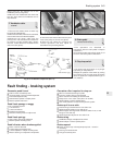
Bleeding - two man method
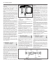
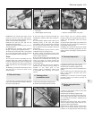
8 Gather together a clean glass jar and a
length of rubber or plastic tubing which will be
a tight fit on the brake bleed screws (photo).
9 Engage the help of an assistant.
10 Push one end of the bleed tube onto the
flrst bleed screw and immerse the other end
of the glass jar which should contain enough
hydraulic fluid to cover the end of the tube.
11 Open the bleed screw one half a turn and
have your assistant depress the brake pedal
fully then slowly release it. Tighten the bleed
screw at the end of each pedal downstroke to
obviate any chance of air or fluid being drawn
back into the system.
12 Repeat this operation until clean hydraulic
fluid, free from air bubbles, can be seen
coming through into the jar.
13 Tighten the bleed screw at the end of a
pedal downstroke and remove the bleed tube.
Bleed the remaining screws in a similar way.
Bleeding - using a one way
valve kit
14 There are a number of one-man, one-way
brake bleeding kits available from motor
accessory shops. It is recommended that one
of these kits is used wherever possible as it will
greatly simplify the bleeding operation and also
reduce the risk of air or fluid being drawn back
into the system quite apart from being able to
do the work without the help of an assistant.
15 To use the kit, connect the tube to the
bleedscrew and open the screw one half a
turn.
16 Depress the brake pedal fully and slowly
release it. The one-way valve in the kit will
prevent expelled air from returning at the end
of each pedal downstroke. Repeat this
operation several times to be sure of ejecting
all air from the system. Some kits include a
translucent container which can be positioned
so that the air bubbles can actually be seen
being ejected from the system.
17 Tighten the bleed screw, remove the tube
and repeat the operations on the remaining
brakes.
18 On completion, depress the brake pedal. If it
still feels spongy repeat the bleeding operations
as air must still be trapped in the system.
Bleeding - using a pressure
bleeding kit
19 These kits too are available from motor
accessory shops and are usually operated by
air pressure from the spare tyre.
Braking system 8•7
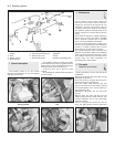
12.8 Caliper bleed screw with dust cap
fitted
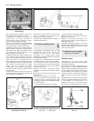
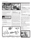
Fig. 8.12 Bleeding a rear wheel cylinder
(Sec 12)
11.3 Front hydraulic hose bracket
8