


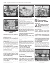
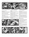

necessary processing (photo). A conventional
paper type air filter element is used and this
must be renewed at the specified intervals.
9 The ECU is specific to the model type, its
function being to control the fuel system
under all operating conditions, including
starting from cold - it richens the fuel mixture
as required but at the same time prevents
flooding. As the engine temperature rises, the
injection impulses are progressively reduced
until the normal operation temperature is
reached.
10 An integral emergency system enables
the fuel injection system to remain operational
in the event of any of the following
components malfunctioning. These items are
the coolant temperature sensor, the air intake
sensor, the Lambda sensor, the idle speed
check actuator and the throttle position
switch. In the event of the throttle position
switch malfunctioning, the fuel system
becomes automatically inoperative.
11 The catalytic converter fitted in the
exhaust system minimises the amount of
pollutants which escape into the atmosphere.
The Lambda sensor in the exhaust system
provides the fuel injection system ECU with
constant feedback which enables it to adjust
the mixture to provide the best possible
conditions for the converter to operate. The
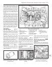
fuel tank ventilation is contained within the
system. This is done by feeding any excess
vapours through a carbon filter back into the
engine intake, using solenoids and valves, as
shown in Fig. 13.46.
Maintenance ¡
12 Regularly check the condition and
security of the system hoses and
connections. Also check the system wiring
connections for condition and security.
13 At the specified intervals, renew the air
cleaner element and the fuel filter.
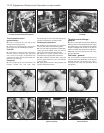
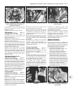
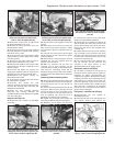
Fuel filter - renewal ¡
14 The in-line fuel filter is secured to the
right-hand suspension turret in the engine
compartment. To remove the filter, first
depressurize the fuel in the system as
described later in this Part.
13•74 Supplement: Revisions and information on later models
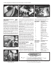
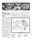
Fig. 13.46 Fuel evaporation control system (Sec 9D)
1 Fuel tank
2 Two-way safety valve
3 Throttle body
4 Two-way vapour vent
valve
5 Vapour cut-off solenoid
6 Carbon filter
7 Elbi solenoid
8 ECU
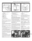
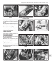
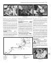
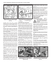
9D.8 Atmospheric air intake for air
temperature sensor (1). Also shown are the
supply and return fuel line connections (2
and 3) and the throttle position sensor (4)
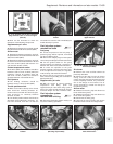
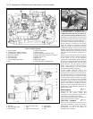
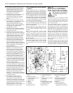
Fig. 13.45 Mono-Jetronic fuel injection component locations in the engine compartment
- 1372 cc ie engine (Sec 9D)
1 Injector resistor
2 Lambda sensor signal connector
3 Lambda sensor heating connector
4 Secondary fuel filter
5 Fuel return pipe
6 Fuel supply pipe
7 Coolant temperature sensor
8 ECU
9 Injector holder turret
10 Lambda sensor
11 Nut for adjusting accelerator cable
12 Engine speed and TDC sensor connector
13 Ignition control unit
14 Ignition coil
15 Diagnostic socket
16 Fuel pump relay and system relay