


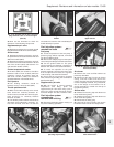
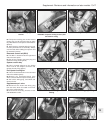
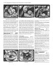
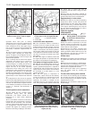

15 Undo the retaining strap bolt and
withdraw the filter from its location bracket.
Disconnect the inlet and supply hose from the
filter. If crimp connectors are fitted they will
have to be cut free and new screw type clips
fitted (photo).
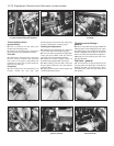
16 Connect the hoses to the new filter
ensuring that the filter is correctly orientated
(the arrow mark on the body indicates the
direction of fuel flow). Ensure that the hose
clips are secure before refitting the filter into
the retaining strap and securing the retaining
bolt. When the engine is restarted, check the
hose connections to ensure that there is no
fuel leakage from them.
Air cleaner element -
renewal ¡
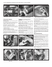
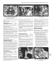
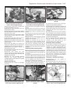
17 Release the spring clip each side at the
front of the air cleaner, then unscrew and
remove the two screws from the top front face
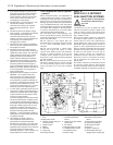
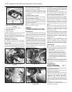
of the housing. Withdraw the end cover and
element from the filter unit (photos).
18 Wipe any dirt from within the casing then
locate the new element and refit it together
with the end cover.
Idle speed and mixture
adjustment ∞
19 No manual idle speed and/or mixture
adjustments to this type of fuel system are
necessary or possible. Any such adjustments
are automatically made by the ECU. If the
engine idle speed and/or mixture adjustment
is suspect, it must be checked using CO
measuring equipment; a task best entrusted
to a FIAT dealer or a competent garage. The
most probable cause of a malfunction is likely
to be a defective sensor or incorrectly
adjusted accelerator control cable.
Accelerator control system
- check and adjustment #
20 To check the adjustment of the
accelerator control system, it is essential that
the engine is at its normal operating
temperature. This is achieved by running the
engine for a period of about fifteen minutes,
by which time the cooling fan should have cut
into operation several times. At this point,
stop the engine, turn the ignition key to the
OFF position and proceed as follows.
21 Remove the air cleaner unit.
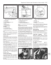
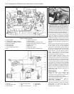
22 Place a 10 mm shim (X) between the
adjustment screw and the cam lever (between
items 1 and 2 in Fig. 13.47), on the throttle
body. This will open the thottle butterfly by
20º.
23 Loosen off the locknuts (C1 and C2) from
each linkage end. Insert another 10 mm
shim (Y) between the cable support bracket
and the nut (C1). Carefully tighten the nut
against the shim, ensuring that the cam does
not move whilst making the cable slightly taut.
24 Remove the shim (Y) and carefully tighten
the nut (C2) against the bracket without
allowing the nut (C1) to move. Remove the
shim (X) and release the accelerator pedal.
Check that the butterfly is completely open
when the the pedal is fully depressed.
Fuel system
depressurisation ¡
Warning: Refer to the beginning
of this Section before starting
any work.
25 The fuel system should always be
depressurised whenever any fuel hoses
and/or system components are disconnected
and/or removed. This can easily be achieved
as follows.
Supplement: Revisions and information on later models 13•75
9D.17B . . . remove the cover and extract
the element
9D.17A Release the air cleaner end cover
retaining clips . . .
9D.15 Secondary fuel filter element
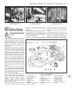
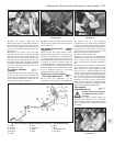
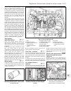
9D.22 Accelerator control rod and cable
connections
A Cable
B Bracket
C1 Locknut
C2 Locknut
D Pulley
E Pawl
H Protection
K Pedal
R Bush
X Shim
Y Shim
1 Adjustment screw
2 Cam lever
13
Fig. 13.47 Accelerator linkage and butterfly control lever - SPi models (Sec 9D)