


20 By connecting a pressurised container to
the master cylinder fluid reservoir, bleeding is
then carried out by simply opening each bleed
screw in turn and allowing the fluid to run out,
rather like turning on a tap, until no air is
visible in the expelled fluid.
21 By using this method, the large reserve of
hydraulic fluid provides a safeguard against
air being drawn into the master cylinder
during bleeding which often occurs if the fluid
level in the reservoir is not maintained.
22 Pressure bleeding is particularly effective
when bleeding “difficult” systems or when
bleeding the complete system at time of
routine fluid renewal.
All methods
23 When bleeding is completed, check and
top up the fluid level in the master cylinder
reservoir.
24 Check the feel of the brake pedal. If it
feels at all spongy, air must still be present in
the system and further bleeding is indicated.
Failure to bleed satisfactorily after a
reasonable period of the bleeding operation,
may be due to worn master cylinder seals.
25 Discard brake fluid which has been
expelled. lt is almost certain to be
contaminated with moisture, air and dirt
making it unsuitable for further use. Clean
fluid should always be stored in an airtight
container as it absorbs moisture readily
(hygroscopic) which lowers its boiling point
and could affect braking performance under
severe conditions.
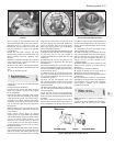
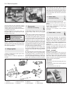
13 Vacuum servo unit -
description
A vacuum servo unit is fitted into the brake
hydraulic circuit on 55 and 70 models in series
with the master cylinder, to provide assistance
to the driver when the brake pedal is
depressed. This reduces the effort required by
the driver to operate the brakes under all
braking conditions.
The unit operates by vacuum obtained from
the induction manifold and comprises basically
a booster diaphragm and non-return valve. The
servo unit and hydraulic master cylinder are
connected together so that the servo unit
piston rod acts as the master cylinder pushrod.
The driver’s braking effort is transmitted
through another pushrod to the servo unit
piston and its built-in control system. The servo
unit piston does not fit tightly into the cylinder,
but has a strong diaphragm to keep its edges
in constant contact with the cylinder wall, so
assuring an air tight seal between the two
parts. The forward chamber is held under
vacuum conditions created in the inlet manifold
of the engine and, during periods when the
brake pedal is not in use, the controls open a
passage to the rear chamber so placing it
under vacuum conditions as well. When the
brake pedal is depressed, the vacuum passage
to the rear chamber is cut off and the chamber
opened to atmospheric pressure. The
consequent rush of air pushes the servo piston
forward in the vacuum chamber and operates
the main pushrod to the master cylinder.
The controls are designed so that
assistance is given under all conditions and,
when the brakes are not required, vacuum in
the rear chamber is established when the
brake pedal is released. All air from the
atmosphere entering the rear chamber is
passed through a small air filter.
Under normal operating conditions, the
vacuum servo unit is very reliable and does
not require overhaul except at very high
mileages. In this case, it is far better to obtain
a service exchange unit, rather than repair the
original unit.
It is emphasised that the servo unit assists
in reducing the braking effort required at the
foot pedal and in the event of its failure, the
hydraulic braking system is in no way affected
except that the need for higher pressures will
be noticed.
14 Vacuum servo unit -
servicing and testing
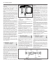
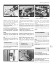
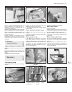
1 Regularly, check that the vacuum hose
which runs between the servo unit and the
inlet manifold is in good condition and is a
tight fit at both ends.
2 If broken or badly clogged, renew the air
filter which is located around the brake pedal
push rod. Access to this is obtained by
disconnecting the pushrod from the
cross-shaft or pedal arm, withdrawing the
pushrod, dust excluding boot and end cap.
3 If the new filter is cut diagonally from its
centre hole, future renewal can be carried out
without the need for disconnection of the
pushrod.
4 If the efficiency of the servo unit is suspect,
it can be checked out in the following way.
5 Run the engine, then switch off the ignition.
Depress the footbrake pedal; the distinctive
in-rush of air into the servo should be clearly
heard. It should be possible to repeat this
operation several times before the vacuum in
the system is exhausted.
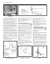
6 Start the engine and have an assistant
apply the footbrake pedal and hold it down.
Disconnect the vacuuum hose from the servo.
There should not be any in-rush of air into the
servo through the connecting stub. lf there is,
the servo diaphragm is probably faulty. During
this test, expect the engine to idle roughly,
unless the open end of the hose to the inlet
manifold is plugged. Reconnect the hose.
7 With the engine off, depress the brake
pedal fully. Start the engine with the brake
pedal still depressed; the pedal should be felt
to go down fractionally.
8 If the results of these tests are not
satisfactory, remove the unit and fit a new one
as described in the next Section.
15 Vacuum servo unit -
removal and refitting
3
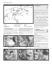
1 Syphon as much fluid as possible out of the
master cylinder reservolr.
2 Disconnect electrical leads from the
terminals in the reservoir cap then uncouple
the rigid pipelines from the master cylinder
body. Be prepared to catch leaking fluid and
plug the open ends of the pipelines.
3 The master cylinder can be unbolted now
from the servo unit, or detached later when
the complete assembly is withdrawn.
4 Working inside the car, disconnect the
servo pushrod from the pedal then remove the
servo mounting nuts.
5 Withdraw the servo assembly into the
engine compartment, then remove it to the
bench. lf the master cylinder is still attached,
cover the wings with protective sheeting, in
case brake fluid is spilled during removal.
6 Refitting is a reversal of the removal
process, but adjust the pushrod clearance as
described in Section 9. On completion of
refitting, bleed the complete hydraulic system
as described in Section 12. Note: Where the
help of an assistant is available, the servo
pushrod need not be disconnected from the
pedal. The rod is a sliding fit in the servo and
the servo can be simply pulled off the rod.
Refitting without having disconnected the rod
from the pedal can be difficult unless the help
of an assistant is available.
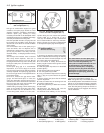
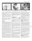
16 Handbrake - adjustment
1
Adjustment is normally automatic, by the
movement of the rear brake shoes on their
automatic adjusters.
However, owing to cable stretch,
supplementary adjustment is occasionally
required at the control lever adjuster nut. The
need for this adjustment is usually indicated
by excessive movement of the control lever
when fully applied.
1 The rear brakes should be fully applied
when the handbrake control lever has been
pulled over four or five notches.
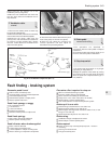
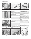
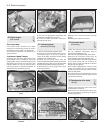
2 If adjustment is required, release the
8•8 Braking system
16.2 Handbrake adjuster nuts