


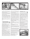

from the suspension struts and then remove
the bolts which secure the hub carriers to the
U-clamps at the base of the suspension
struts.
23 Pull the tops of the hub carriers down and
then outwards and push the driveshafts from
them.
24 Unbolt the driveshaft inboard boot
retainers and then remove the driveshafts
from the transmission.
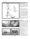
25 Support the engine on a hoist or use a
trolley jack under the engine/transmission.
Remove the bottom mounting and then the
upper left and right-hand ones.
26 Lower the power unit to the floor by
pushing it to the left-hand side to clear the
right-hand mounting bracket and then swivel
the gearbox towards the rear of the car.
Withdraw the engine/transmission from under
the car.
27 External dirt and grease should now be
removed using paraffin and a stiff brush or a
water-soluble solvent.
28 Unbolt and remove the engine mounting
brackets and the starter motor.
29 Unbolt and remove the cover plate with
the gearchange ball stud strut from the lower
front face of the flywheel housing.
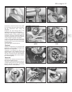
30 With the engine resting squarely on its
sump pan, unscrew the flywheel housing
connecting bolts, noting the location of any
lifting lugs and hose and wiring clips.
31 Support the weight of the transmission
and withdraw it in a straight line from the
engine.
36 Engine - dismantling (general)
Refer to Section 14, Part 2.
37 Engine ancillary components
- removal
Refer to Section 15, Part 2 and also remove
the intake manifold.
38 Engine -
complete dismantling
3
1 Have the engine resting squarely and
supported securely on the work surface.
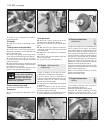
2 Unbolt and remove the timing belt cover.
3 Grip the now exposed timing belt with the
hands and loosen the camshaft sprocket.
4 Release the timing belt tensioner pulley
centre bolt, then slip the belt from the pulley
and sprockets to remove it. Note which way
round the belt is fitted, usually so that the
lettering on the belt can be read from the
crankshaft pulley end of the engine.
5 Remove the camshaft sprocket.
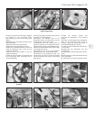
6 Unbolt and remove the camshaft timing belt
cover backing plate.
7 Unbolt and remove the camshaft carrier
cover.
8 Unbolt the camshaft carrier and lift it off
very slowly, at the same time pushing the cam
followers and their shims down with the
fingers securely onto their respective valve
springs. It is easy to remove the camshaft
carrier too quickly with some of the cam
followers stuck in it and as the carrier is lifted
away, the cam followers will fall out. If this
happens, the valve clearances will be upset as
the cam followers and shims cannot be
returned, with any certainty, to their original
positions. Keep the cam followers and shims
in their originally fitted order.
9 Unscrew and remove the cylinder head
bolts and nuts, grip the manifold, rock the
head and remove the complete cylinder
head/manifold/carburettor assembly. Remove
and discard the cylinder head gasket.
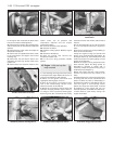
10 Unbolt the coolant pump from the side of
the cylinder block and remove it complete
with coolant distribution pipe. Remove the
crankcase breather.
11 Remove the distributor/oil pump
driveshaft. This is simply carried out by
inserting a finger into the hole vacated by the
distributor and wedging it in the hole in the
end of the driveshaft. Lift the shaft out of
mesh with the auxiliary shaft. Where the
distributor is driven by the camshaft, a cover
plate retains the oil pump driveshaft in
position.
12 Unbolt and remove the sprocket from the
end of the auxiliary shaft. The sprocket is held
to the shaft with a Woodruff key.
13 Unbolt the auxiliary shaft retainer and
withdraw the shaft from the crankcase.
14 Unscrew and remove the crankshaft
pulley nut. This is very tight and the flywheel
starter ring gear will have to be jammed with a
cold chisel or a suitably bent piece of steel to
prevent the crankshaft rotating.
15 Withdraw the crankshaft sprocket, which
is located by the Woodruff key.
16 Unbolt the front engine mounting bracket
from the cylinder block, together with the
timing belt cover screw anchor bush. Unbolt
and remove the timing belt tensioner pulley.
17 Unscrew the flywheel securing bolts. The
starter ring gear will again have to be jammed
to prevent the crankshaft rotating as the bolts
are unscrewed. Mark the flywheel position in
relation to the crankshaft mounting flange,
then remove it.
18 Unbolt the front and rear crankshaft oil
seal retainer bolts from the crankcase and the
sump. Remove the oil seal retainers.
19 Turn the engine on its side, extract the
remaining sump bolts and remove the sump.
If it is stuck, try tapping it gently with a
soft-faced hammer. If this fails, cut all round
the sump-to-gasket flange with a sharp knife.
Do not try prising with a large screwdriver; this
will only distort the sump mating flange.
20 With the sump removed, unbolt and
remove the oil pump.
21 Grip the oil pick-up pipe and twist or rock
it from its hole in the crankcase. It is an
interference fit in the hole.
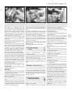
22 Remove the piston/connecting rods as
described in Section 32.
23 Before unbolting the main bearing caps,
note that they are marked with one, two, three
or four notches. No. 5 main bearing cap is
unmarked. Note that the notches are nearer
the auxiliary shaft side.
24 Unbolt and remove the main bearing
caps. If the bearing shells are to be used
again, tape them to their respective caps. The
bearing shell at the centre position is plain,
the others have a lubricating groove.
25 Carefully, lift the crankshaft from the
crankcase, noting the thrust washers at No. 5
main bearing. These control the crankshaft
endfloat.
39 Cylinder head - dismantling
and decarbonising
4
1 The operations are similar to those
described for the ohv engine in Section 17 in
respect of decarbonising and valve grinding.
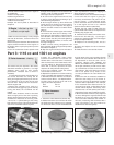
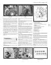
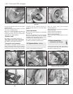
2 To remove a valve, use a valve spring
compressor to compress the first valve and
then extract the split collets (photo).
3 Release the valve spring compressor.
4 Withdraw the valve spring cap and the
double valve springs (photos).
5 Remove the valve (photo).
1•28 1116 cc and 1301 cc engine
39.4A Valve spring cap39.2 Valve spring compressor and split
collets