


Initial start-up after major
overhaul
28 Refer to Chapter 1, Section 45, but note
that an oil pressure gauge is fitted to indicate
oil pressure.
29 Check the ignition static timing as
described in Section 10.
30 Check the engine idle speed and CO level
as described in Section 9.
7 Engine -
1372 cc ie and 1372 cc
Turbo ie
PART A: GENERAL
Description
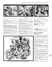
1 The 1372 cc engine is similar in design to
the OHC engine fitted to the FIAT Tipo
variants. The engine is of four-cylinder, in-line,
overhead camshaft type, mounted
transversely at the front of the vehicle.
2 The crankshaft runs in five main bearings.
Thrustwashers are fitted to the rear (flywheel
end) main bearing in order to control
crankshaft endfloat.
3 The connecting rods are attached to the
crankshaft by horizontally split shell-type
big-end bearings. The pistons are attached to
the connecting rods by fully-floating gudgeon
pins which are secured by circlips. The
aluminium alloy pistons are fitted with three
piston rings: two compression rings and an oil
control ring.
4 The camshaft is driven by a toothed belt
and operates the valves via bucket and shim
type cam followers. The camshaft is located in
a separate housing on top of the cylinder
head.
5 The inlet and exhaust valves are each
closed by double valve springs, and operate
in guides pressed into the cylinder head.
6 The auxiliary shaft, which is also driven by
the toothed belt, drives the oil pump.
7 Lubrication is by means of a gear type
pump which draws oil through a strainer
located in the sump, and forces it through a
full-flow filter into the engine oil galleries from
where it is distributed to the crankshaft,
camshaft and auxiliary shaft. The big-end
bearings are supplied with oil via internal
drillings in the crankshaft. The undersides of
the pistons are cooled by oil spray nozzles
located in each main bearing location in the
crankcase.
8 A crankcase ventilation system is
employed, whereby piston blow-by gases are
drawn via an oil separator into the air cleaner,
from where they are drawn into the inlet
manifold and re-burnt with fresh air/fuel
mixture.
9 The 1372 cc ie engine is fitted with a Bosch
Mono-Jetronic single point fuel injection (SPi)
system. Whilst the higher performance
1372 cc Turbo ie engine is fitted with a Bosch
L3.1 (L3.2 from 1992) Jetronic multi-point
injection (MPi) system and turbocharger with
intercooler and oil cooling. The L3.2 system
models are fitted with catalytic converters.
Maintenance ™
10 At the intervals specified in Section 3 or
“Routine maintenance” at the beginning of
this Manual, carry out the following tasks.
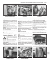
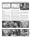
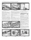
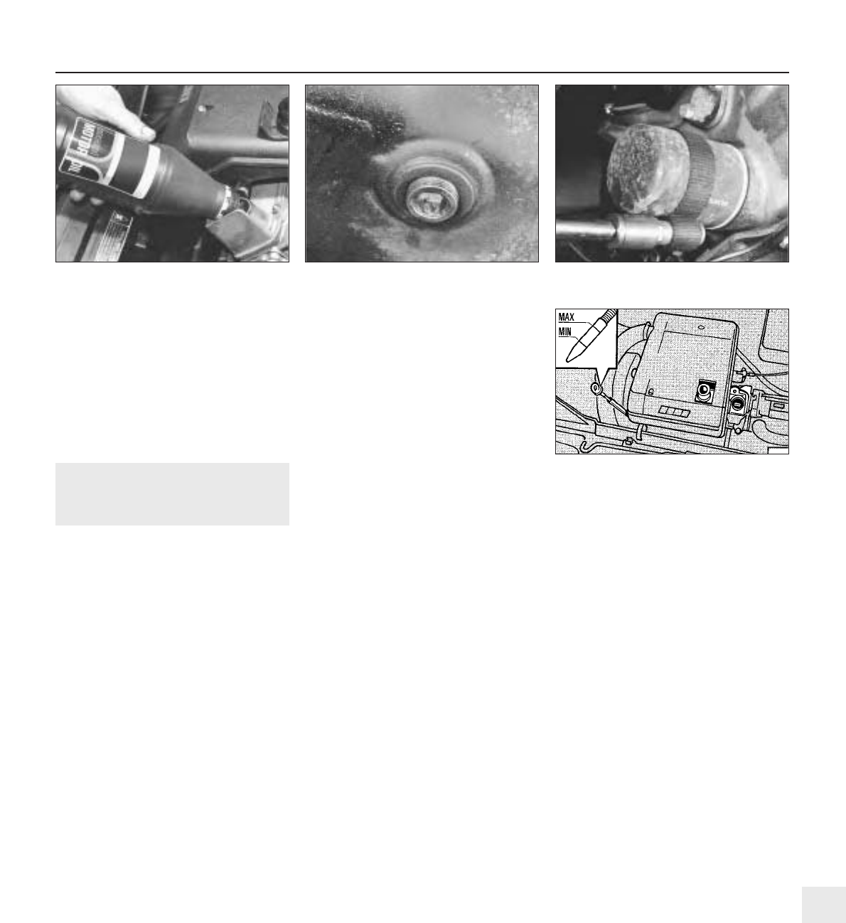
11 Check the engine oil level as follows. With
the vehicle parked on level ground, and with
the engine having been stopped for a few
minutes, withdraw the oil level dipstick, wipe it
on a clean rag, and re-insert it fully. Withdraw
the dipstick again and read off the oil level
relative to the MAX and MIN marks. The oil
level should be between the marks. If the level
is at or below the MIN mark, top up through
the filler on the camshaft cover without delay
(photo). The quantity of oil required to raise
the level from MIN to MAX on the dipstick is
approximately 1.0 litre (1.8 pints). Do not
overfill.
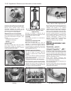
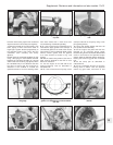
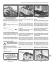
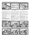
12 Renew the engine oil and filter as
described in Section 2 of Chapter 1 (photos).
13 Check and if necessary adjust the valve
clearances as described in Part B of this
Section.
14 Inspect the engine for signs of oil, coolant
or fuel leaks and rectify as necessary.
15 Inspect the crankcase ventilation hose for
blockage or damage. Clean or renew as
necessary.
16 Check the condition and tension of the
timing belt as described in Part B of this
Section.
17 Renew the timing belt as described in
Part B of this Section.
PART B:
OPERATIONS POSSlBLE
WITH ENGINE IN CAR
Valve clearances -
checking and adjustment #
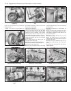
1 It is important to ensure that the valve
clearances are set correctly, as incorrect
clearances will result in incorrect valve timing
thus affecting engine performance.
2 The clearances must be checked and
adjusted with the engine cold.
3 On the ie engine, refer to Section 9 in this
Chapter for details and remove the air cleaner
unit.
4 On the ie engine disconnect the crankcase
ventilation hose from the injector unit and
position the hose out of the way.
5 On Turbo ie engines, loosen off the clips
and remove the air hose to the inlet manifold
(above the camshaft cover).
6 On Turbo ie engines, disconnect the
accelerator cable from the throttle housing
and the support bracket on the camshaft
cover.
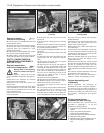
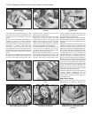
7 Unscrew the securing nuts and washers
and remove the camshaft cover, noting that
on later models two of the nuts also secure
the hose clip assembly. Recover the gasket.
8 Numbering from the front (timing belt) end
of the engine, the exhaust valves are 1, 4, 5
and 8, and the inlet valves are 2, 3, 6 and 7.
Supplement: Revisions and information on later models 13•37
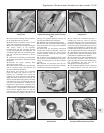
7A.12B Engine oil filter removal using a
strap wrench - 1372 cc engine
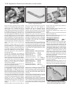
7A.12A Engine sump drain plug - 1372 cc
engine
7A.11 Topping up the engine oil level -
1372 cc engine
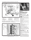
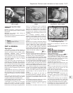
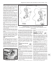
Fig. 13.15 Engine oil level dipstick location
and level markings on the 1372 cc ie and
Turbo ie engines (Sec 7A)
13